diy solar

diy solar

Batteries not having the expected capacity?, or maybe my numbers are very bad?.

mrdavvv

Solar Enthusiast
Joined
Jan 14, 2020
Messages
404
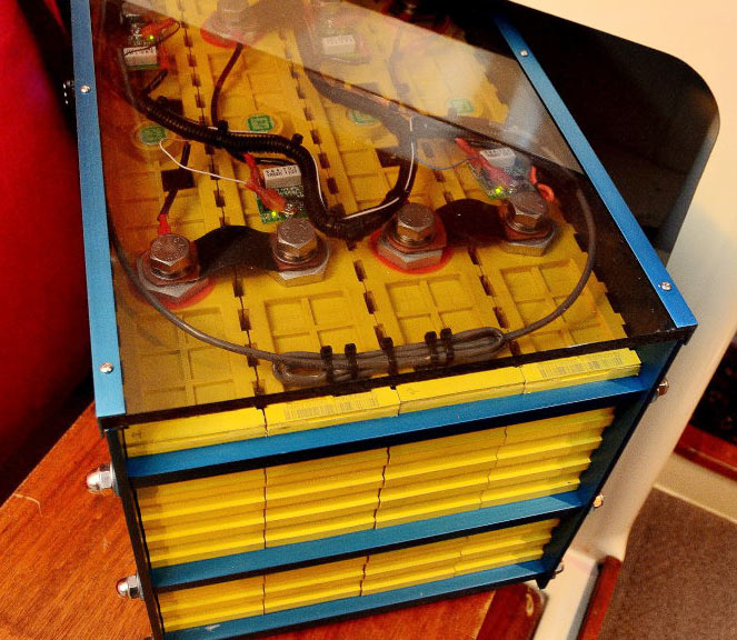
So im doing some testing in my system with the newly arrived 280AH LifePO4:

1588095028264.png

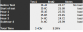
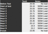
And this are my test numbers:

1588095473129.png

As you can see, i'm getting 3 and a half hours with a 500W load, so around 1750Whr, and considering the 50W that the inverter takes and some losses from efficiency and cabling its probably near 2000W.... But i think i should be getting at least somewhere around 4000Whr?.

  • 24V @280Ah = 6720W
  • Charge / Discharge Profile 20 to 80%
  • So using 60% of full capacity = 4000W

This are my inverter configurations (Based on this video from will
):

1588096602071.png


----------------------------------------------
Question 1.

What are the recommended numbers for charging / discharging?. In Will's site i found this other config:

1588096609303.png

I think this is for 10 - 90% State of charge?, maybe i should bottom balance and better use this setup?.
----------------------------------------------
Question 2.
Maybe im not completely charging the batteries?, The inverter has this option:

1588096788892.png

I placed it at FULL, but you can also setup an specific voltage. I notice that i get full charging at the beginning (40A), and then after some hours it keeps getting low, until i have around 4 -8A and after its charged it goes to float voltage at 24@1A
----------------------------------------------
Question 3.
What happens with the floating voltage?. Its my understanding that once the battery is charged, you dont need to introduce more voltage. And after "Fully" charging the battery i can see that the charger its injecting to the battery 1A@24V permanently, its this the recommended config and behavior?
----------------------------------------------
Question 4.
Overall, are my numbers good, or what i could be doing wrong?.
 

Attachments

  • 1588095428678.png
    1588095428678.png
    11.6 KB · Views: 5
  • 1588095764471.png
    1588095764471.png
    4.9 KB · Views: 5
FYI, 3.2x8x280 = 7168 watt hours.

26.47 = 70% ish SOC according to this chart here: https://diysolarforum.com/threads/lifepo4-voltage-chart.3156/

On this page, recommended
24V LiFePO4 Battery w/ BMS
  • Absorption: 29V
  • Float: 27.2V
  • Inverter Cut-off: 21.4V-24V

Other than that, I'll let someone with more experience chime in with some answers.
 
Last edited:
No expert, but with lifepo4's discharge curve so flat in the 26 - 26.5v range, it's hard to judge 80%, or any state of charge. A 28.2v max charge voltage seems good, as you mentioned from Will's video. I charge only to 28v, which does keep me very roughly 10% short of a "full" charge, on purpose. But there's a lot of charging available between 26.5v and 28v, so I'd try the higher max voltage before condemning the battery(ies). I'm not familiar with your controller - if there's no lifepo4 preset, then setting the boost voltage manually (question 2) is probably best. Also, after resting the pack disconnected after a charge for a while, are the individual cell voltages staying pretty consistent?

You don't need float or equalization voltages to be set, they're not needed. But if the controller wants them set, make sure they're less than the boost voltage.
 
Youre probably under charging. Try setting until 29.2v AT THE TERMINAL. that may take a setting of 29.3v-29.4v at controller.

You also need to show no load voltage after test. Youre likely seeing voltage sag.
 
Do not have your inverter, i have the lv5048. With mine i have to set the inverter to user bat selection, then you can program bulk and float voltages. Then in menu 32 you can set absorbtion time. For the lv5048 the absorotion clock starts counting down is triggered once the battery voltage get to be higher then the float voltage. So if you set bulk at say 27.7v and a float voltage of 26.7 and if you have menu 32, a safe absorbtion time could be set to 2 hours to start. Watch the voltages and make sure non of the cells go over 3.65v during absorbtion.

I have tried auto in menu 32, in auto the batts never get close bulk voltage. Tried one hour in menu 32 and the charger goes to float one hour after it passes float voltage. You would think you could just set it to a bulk voltage and program a 5 minute absorbtion time and be done.

Hopefully i am not confusing the question..
 
Youre probably under charging. Try setting until 29.2v AT THE TERMINAL. that may take a setting of 29.3v-29.4v at controller.

You also need to show no load voltage after test. Youre likely seeing voltage sag.

Most likely, im doing a new test today with 28.2 as charging voltage, as i want to leave some margin at the top and bottom of the cells. The no load voltage at the end of the test es 24.5V, and underload is 24V. But i think that if i want the cutoff to be 24V, it should be underload, since for example you place it low enough, you might get lower than 2.5V underload.... however i adjusted it now at 22V and see how it goes.

Do not have your inverter, i have the lv5048. With mine i have to set the inverter to user bat selection, then you can program bulk and float voltages. Then in menu 32 you can set absorbtion time. For the lv5048 the absorotion clock starts counting down is triggered once the battery voltage get to be higher then the float voltage. So if you set bulk at say 27.7v and a float voltage of 26.7 and if you have menu 32, a safe absorbtion time could be set to 2 hours to start. Watch the voltages and make sure non of the cells go over 3.65v during absorbtion.

I have tried auto in menu 32, in auto the batts never get close bulk voltage. Tried one hour in menu 32 and the charger goes to float one hour after it passes float voltage. You would think you could just set it to a bulk voltage and program a 5 minute absorbtion time and be done.

Hopefully i am not confusing the question..

Weird!, my "32" menu is some timer. Just checked the LV2424 against the LV5048 manual and indeed their menus are different. I dont have this setting:

1588169434489.png

Someone in the forum mentioned that the LV5048 its just 2x2024 stick together, but as we can see they have their software diferences!. Anyways, i cannot edit that timer. Do you have any idea of how the charge algorithm works in FULL mode (Guess is the default on my inverter).
 
im doing a new test today with 28.2 as charging voltage, as i want to leave some margin at the top and bottom of the cells.

How are you balancing your cells if youre not fully charging? How are you supposed to determine capacity if youre starting at a random discharged state?
 
How are you balancing your cells if youre not fully charging? How are you supposed to determine capacity if youre starting at a random discharged state?
  • What the BMS consider fully charging?. I have the Daly BMS and i still dont know at what voltage they start to balance. Need to check on this but seems like there is not datasheet fromt he manufacturer. Somewhere around his forum a member mentions that it start to balance >28.0V, but not confirmend (I will search for this comment).
  • It was not really that random, i was considering the 26.6V that will mentions in the video that i attached in OP... he says to configure to 26.6V to achieve 80% charge (Maybe i didnt get it right). But as @Fred S mentios, its probably not the best idea since that voltage its not very good to determine SOC
 
Almost every drop in battery manufacturer recommends at least 3.6v per cell. And most 3.65v. @Fred S is right, its practically useless. You need a shunt monitor. Charge to 3.65v then set monitor to 100%.

Then we can get to the bottom of battery capacity.
 
So i did charge with 28.2V and the battery took 50A for several hours, so indeed i was undercharging them by a LOT.

This was the new test, they weren't fully charged in reality.... but with this i have the right idea and i know they are giving close to rated capacity:

1588630178775.png

Total: 4500W for 9 Hours.

When i manage to get a coulumb meter i will do a proper capacity test.

Thanks all for the advice!
 

Attachments

  • 1588630075845.png
    1588630075845.png
    11.1 KB · Views: 7
Almost every drop in battery manufacturer recommends at least 3.6v per cell. And most 3.65v. @Fred S is right, its practically useless. You need a shunt monitor. Charge to 3.65v then set monitor to 100%.
I get where you are here completely. I have a couple questions about what happens next.

As shown in mrdavvv's diagram, "Before test 26.56v", here the cell voltage is 3.32v.

What does the monitor show in regards to the SOC% or number of ah that have dissipated from when the monitor was set to 100% ?

To explain this a little in case its not clear what I am asking: The voltage where the monitor is set to 100% is 3.65v/cell. I am assuming the surface charge dissipated and by the time the mrdavvv's test was about to begin. At which point the voltage was 3.32v/cell. What does the monitor show to account for this in terms of SOC% and ah used?
 
Last edited:

I find this to be a very good read and advice to take in.
 
I get where you are here completely. I have a couple questions about what happens next.

As shown in mrdavvv's diagram, "Before test 26.56v", here the cell voltage is 3.32v.

What does the monitor show in regards to the SOC% or number of ah that have dissipated from when the monitor was set to 100% ?

To explain this a little in case its not clear what I am asking: The voltage where the monitor is set to 100% is 3.65v/cell. I am assuming the surface charge dissipated and by the time the mrdavvv's test was about to begin. At which point the voltage was 3.32v/cell. What does the monitor show to account for this in terms of SOC% and ah used?

Its doesnt really matter for monitor calibration. Either charge to 3.6 or 3.65v or let it settle to 13.5v. Then set the controller to 100% and it will go down and up based on amps through the shunt. Voltage plays no role
 
But i think i should be getting at least somewhere around 4000Whr?.
Check you assumptions. It has probably already been said but the only way to test capacity on a cell is to charge it to the top and discharge it to the bottom. Any assumption that x voltage equals a pecentage of SOC is only going to compound that error. If you are only getting 1750 Watts out of a group of cells that should have a capacity of 7 kWhs then there are only two possibilities. One, your voltage assumptions about capacity are wrong, or two, your cells do not have 7 kWhrs of capacity. Both of those are only hypothoses not conclusions. Those hypotheses need to be tested to reach a conclusion. Sorry if I am repeating what has already been said but my eighth grade science teacher left me with a love of science and I try to use scientific thinking skills when I am able.
 
You know, its kind of funny, as I too keep testing "assumptions" and "theories" as I experiment to refine my low income system. Its well known that LI lasts longer when you limit charge to 90%, and as an AGM user, I can honestly say, the last 10% to fill my AGM's is the hardest, but has huge capacity. I don't remember finding any "concrete" evidence of the exact percentage of charge in that last 10% for either AGM or LI, but, I bet you, its huge in proportion from personal experience with my AGM's. Even the math suggests that the higher voltage alone will have an impact on the work its able to do.

For LFP there is very little in the last 10%. A voltage chart shows this where you are above the upper “knee” on the graph. Voltage spikes with very little additional energy. Overcharging can happen very quickly here.

Quite different from AGM.
 
No fire hazard with LiFePO4. You will just ruin your battery.

Now imagine that voltage spike in reverse as you discharge the battery. Very little work can be done in the seconds it takes to drop back down that exponential part of the curve. All risk, no reward there.

Read this if you want some great info:


AGMs are a different animal.
 
but I still don't see the reading of actual energy storage. How much work it can actually do in comparison to say, between 50 and 60% charged
If you look at the scale on the bottom it is State of Charge. You can see that the voltage is fairly flat from 50 to 60% at a constant current, if that is what you mean by, "how much work can it actually do"?
To answer your other question about that last 10% you can see the difference between stopping charge at 4v (100%) and stopping at 3.6 (approx 97%).
 
Last edited:
Back
Top