• Have you tried out dark mode?! Scroll to the bottom of any page to find a sun or moon icon to turn dark mode on or off!

diy solar

diy solar

LiFePO4 Voltage Chart?

TommyG-UK

Photon catcher
Joined
Dec 29, 2019
Messages
5
Location
South Wales, UK
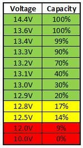
Hi guys, I was looking through the mobile-solarpower.com website, and on this page I found a battery voltage chart for LiFePO4 batteries.
msf4vpdl-1_14.jpg

But I noticed it wasn't showing the exact voltage ranges that my battery data sheet does.
My data sheet shows 100% charge at 14.6V and 0% charge at 10.0V.

Battery Model100Ah 3.2V
Nominal Voltage3.2V
Standard Charging Current0.5C (50A)
Standard Discharging Current0.5C (50A)
Fast Charging1C (100A)
Charging End Voltage3.65V (14.6V)
Discharge End Voltage2.5V (10.0V)
Charge Temperature Range0 - 55°C
Discharge Temperature Range-20 - 55°C
Max Cont. Discharge Current1C (100A)
Max Burst Discharge Current3C (60sec) (300A)
Impedance<045mΩ
Screw TerminalM6
Weight2.2Kg (8.8Kg)

I thought that maybe I could make my own voltage chart more suited to my battery's specifications, shown below.

Capacity %Pack VoltageCell Voltage
100%14.603.65
99%14.453.61
95%13.873.46
90%13.303.32
80%13.253.31
70%13.203.30
60%13.173.29
50%13.133.28
40%13.103.27
30%13.003.25
20%12.903.22
17%12.803.20
14%12.503.12
9%12.003.00
0%10.002.50

I was wondering if someone could cast their eye over it and let me know if anything needs to be changed. I'm a beginner at this so would like to learn how to be accurate when making the voltage chart.
Thanks.
 
Using voltage is a moving target with lfp being so linear. Now if you're having the batteries sit for a period of time with no load or charge then you could get an estimate but if you will have some sort of load/ charge happening the charts are not accurate. ;)
 
The companies manufacturing the batteries aren't manufacturing the cells inside so they post their recommendations or interpretations of the cell manufacturers data sheet. I think lifepo4 is lifepo4 is lifepo4 and we all should decided what voltage that chemistry likes. There isn't a lot of AH above 13.3 so i don't charge mine over 13.8 but i think that might not be the right choice because the internal bms probably balances the cells by dissipation at a higher set point. What i have chosen is to set the charge limit to 13.8 and then once a month charge to 14.4 to re balance. I think this will give the longest life. The chart you posted is the closest way to guestimate SOC by voltage but you can see that there isn't much capacity above 13.35 so why push above that (other than to balance)? You can actually over charge them at 13.86 if left charging at that voltage long enough.
 
SOCVCellMy LimitsMy LimitsMy LimitsMy Limits
48V setupSelf imposedSelf imposedSelf imposedSelf imposed
12V Setup24V Setup48V Setup
100.00%58.403.653.29413.226.452.7
99.50%55.203.45
99.00%54.003.38
90.00%53.603.353.27713.126.252.4
80.00%53.203.333.26013.026.152.2
70.00%52.803.303.24213.025.951.9
60.00%52.403.283.22512.925.851.6
50.00%52.203.263.20812.825.751.3
40.00%52.003.253.19112.825.551.1
30.00%51.603.233.17312.725.450.8
20.00%51.203.203.15612.625.250.5
14.00%50.403.15
9.50%48.003.003.15612.625.250.5
5.00%44.802.80
0.50%40.602.54
0.00%40.002.502.95011.823.647.2


2020-01-04.png
My self imposed limits are based on what the cells return to after a bulk charge. For the first month, I was bulk charging to 3.55V per cell, they always returned to 3.295V on their own, so why try to force them. Let them be happy at 3.295 and "call it 100%".

These are for USED cells.

New cells are just that. Battleborn expressly states to use them 100 to 0, but charging them to 90 will let the cells last far far longer. It takes 3 times more time to go from 80% to 100% as it does from 0% to 80%. But it takes about 30 minutes to go from 100% to 80%, and 24 hours to go from 80% to 0%.

I set my 0% SOC at the top of the slope down to zero at about 15% SOC actual, I simply don't use that very low end so I can avoid further degradation. LiFePO4 cannot be fixed once degraded, it's a one-way process.

 
Last edited:
What size load were you discharging at to figure this?

Not sure what you mean about the 3 times more time comment.

I would think that most folks aren't using the cells lower end of SoC unless maybe they're bottom balanced or they're are away from the batteries, then you better have your bms set to protect the cells.
 
Word of advice.

When your batteries are full, take a voltage reading @ the battery terminals, take a voltage reading at your SCC and again at the Inverter. There will be a difference between them all, not huge but there nevertheless. As shown above .2V can make a difference ! .40 can be 10% !! Verify that the SCC & Inverter see the same voltage by calibrating the devices to compensate for the difference.

If you want to be sure that LVD disconnects at say 22.0V exactly (at the battery of course) then the inverter should have that - the loss, so if the terminals at the Inverter says 21.6 when the battery is at 22.0 then the inverter should shutdown at 21.6. Same goes for charging & HVD which you don't want to cross. Every connection, terminal, shunt, breaker / fuse will affect the voltage slightly, even length & grade of wire will do it.
 
What size load were you discharging at to figure this?

Not sure what you mean about the 3 times more time comment.

I would think that most folks aren't using the cells lower end of SoC unless maybe they're bottom balanced or they're are away from the batteries, then you better have your bms set to protect the cells.
If it takes 1 hour to get to 80%,it takes 3 hours to get to 100% from 80%

I usually have a 1500 watt load for a 8 hour continuous drain, running my entire house.
 
If it takes 1 hour to get to 80%,it takes 3 hours to get to 100% from 80%

I usually have a 1500 watt load for a 8 hour continuous drain, running my entire house.

That makes no sense. Couloumbic charge efficiency of LiFePO is about 100%. If you are charging with a constant current from 0% to 100% the last 20% (from 80% to 100%) takes exactly 20% of the time.

If you are trying to define your point of 80% charge from your table of voltages above, you are just fooling yourself. If you are not in the top or bottom "knees" of the curve, you need to have the cell resting for many hours before you can get any idea of charge state from voltage. Even then, it's extremely blunt.
 
Maybe being used cells from ev (I think I remember he said they came from buses?) they have a higher resistance now.

But it didn't/ doesn't make sense to me either?

I know I could just about put a stop watch on my batteries when charging at a set 100a from whatever SoC. Meaning for my batteries 1% = 5ah, so from 80%-100% SoC takes 1 hour to charge or 60%-100% takes 2 hours as I said I could almost time within minutes with a stopwatch. But again being at 100% isn't necessary so working in PSoC works just fine. This is near 4 years of observing it.
 
Last edited:
That makes no sense. Couloumbic charge efficiency of LiFePO is about 100%. If you are charging with a constant current from 0% to 100% the last 20% (from 80% to 100%) takes exactly 20% of the time.

If you are trying to define your point of 80% charge from your table of voltages above, you are just fooling yourself. If you are not in the top or bottom "knees" of the curve, you need to have the cell resting for many hours before you can get any idea of charge state from voltage. Even then, it's extremely blunt.
It's OK that it doesn't make sense. It simply is the way it is..
 
I'm fairly certain that you are misunderstanding your cells. If you want to explain your measurements in more detail, I'd be glad to be shown wrong.

Just simply observing and waiting for the charge to be higher.

Yes, I get it the resistance getting much much higher as the cause. That's why they are so much less expensive as used, and frankly why they are not still being used where they were installed.
 
Thanks for the chart Jason. Very informative as it relates to these specific BYDs. Do you have a steady charge rate (x amps) that you used in that chart @ 48v? Or was it variable solar. I'll be charging my BYDs (3 of the preassembled 130a TechDirect units) @24v, so I really appreciate the conversions you listed.
 
Just simply observing and waiting for the charge to be higher.

Yes, I get it the resistance getting much much higher as the cause. That's why they are so much less expensive as used, and frankly why they are not still being used where they were installed.

By what metod are you measuring the state of charge?
 
Thanks for the chart Jason. Very informative as it relates to these specific BYDs. Do you have a steady charge rate (x amps) that you used in that chart @ 48v? Or was it variable solar. I'll be charging my BYDs (3 of the preassembled 130a TechDirect units) @24v, so I really appreciate the conversions you listed.
I am charging with grid-tied solar, so basically grid power. I have off-grid about ready to get installed in the next few weeks. I plan to set up the MPP Solar LV5048 to charge only from solar. I expect it is more than enough to charge the batteries, my end game is to go entirely off-grid with about 8 kWp.

I have been bulk charging at 56.5V@16amps which is 3.53V@0.25amp per cell. (16s4p) Since these are very used cells, mine self-discharge, so I float them at 52.9V.
 
Last edited:
I'm fairly certain that you are misunderstanding your cells. If you want to explain your measurements in more detail, I'd be glad to be shown wrong.

I think JASONHC is correct ...

Charging LiFePO4 is a two step process … FIRST step uses constant current (CC) to reach about 60% State of Charge (SOC); And then STEP 2 kicks in until the charge voltage reaches 3.65V per cell. Turning from constant current (CC) to constant voltage (CV) means that the charge current is limited by what the battery will accept at that voltage, so the charging current tapers down asymptotically.

If you had to time the process – STEP ONE (60% SOC) needs about one hour and the STEP 2 (40% SOC) needs another two hours .. I have seen it that way ever since I started working with LiFePO4
How long should it take me to charge a 280ah 12v battery from 20% - 80% with a 45amp smart charger? The charger tops out at 13.6 volts.
 
Just read some interesting stuff about my charger. Please let me know if this is the proper charging method for Lifepo4 batteries. Thanks!

PD9245CV 9200 - The full rated load is available for load, battery
charging or both. When functioning as a regulated
battery charger the converter has a nominal voltage
output of 13.6 VDC for 12 volt models and 27.2 VDC
for 24 volt models. The system is designed to sense
voltage on the battery and automatically selects one
of three operating modes (normal, boost and storage)
to provide the correct charge level to the batteries.

BOOST MODE: If the converter senses that the
battery voltage has dropped below a preset level the
output voltage is increased to approximately 14.4
VDC (28.8 VDC for 24 volt models) to rapidly
recharge the battery.

NORMAL MODE: Output voltage set at
approximately 13.6 VDC (27.2 VDC for 24 volt
models).

STORAGE MODE: When the converter senses that
there has been no significant battery usage for 30
hours the output voltage is reduced to 13.2 VDC
(26.4 VDC for 24 volt models) for minimal water
usage. When in storage mode the microprocessor
automatically increases the output voltage to 14.4
VDC (28.8 DC for 24 volt models) for approximately
15 minutes every 21 hours to help prevent sulfation
of the battery plates.
 
I think JASONHC is correct ...

Charging LiFePO4 is a two step process … FIRST step uses constant current (CC) to reach about 60% State of Charge (SOC); And then STEP 2 kicks in until the charge voltage reaches 3.65V per cell. Turning from constant current (CC) to constant voltage (CV) means that the charge current is limited by what the battery will accept at that voltage, so the charging current tapers down asymptotically.

If you had to time the process – STEP ONE (60% SOC) needs about one hour and the STEP 2 (40% SOC) needs another two hours .. I have seen it that way ever since I started working with LiFePO4

At what C-rate are you charging if you get to only 60% SoC before entering the CV state? With charge rates < 1C my experience is to get almost full cells before switching to CV mode, and with a very quick current taper after that.
 
As in a voltage vs SoC table? Such a table only makes sense if the cells are well rested. During charge, it means nothing.
All tables are for reference.

The forest we are in is battery charging.

The tree we are looking at is a used Lifepo4 tree.

In the forest of battery charging all batteries charge to match the voltage they are presented with, at the amperage they can absorb. The voltage potential (difference in battery and source of voltage) is all that there is.

What ever you decide the top limit to be is the decision to make. There is brand new limit, and of course there is everything else, which is determined by any number of unlimited factors. Only a brand new lifepo4 battery will get to use a brand new factory table, everything else is less.

Most lifepo4 cells come with 3000 cycle 0% to 100% warranties. As soon as you operate those cells in the 20% to 80% range their longevity becomes all but irrelevant, ie nearly infinite cycles are possible. Furthermore, by operating a lifepo4 battery, within the 20%-80% a cycle is never even actually recording as even happening.

I have operated 30 days straight and "cycled" twice a day in the 20%-80% range of the new table, and not even one recorded cycle completed by the bms. The usage AH from the day to day shows a discharge of about 45 to 55 AH @ 48v setup. The bms registers that the SOC goes from 92% to 86%. That's when telling the bms that the battery is 800 AH and 48v setup. The actual physical battery is 260 Ah though.
 
You are fooling yourself. If you want to know the state of charge of a cell without letting it rest for a long time, you need to do Coulomb counting. Trying to gain information from cell voltage while charging and comparing that to a table of resting cell voltages is nonsensical. I'll leave you to your illusions and remain in the real world...
 

diy solar

diy solar
Back
Top