LukeL
New Member
Sorry in advance for all the ignorance from me on this. I’m caught in a trap that I had no intention of entering. Assumed I could swap out LA battery bank for Lifepo4 from China. Battery for battery 48v system. Have lived Offgrid for 6 years. Need help.
Anything really (preferably a wiring diagram in English). I’ve watched several videos from Andy (offfrid garage) by necessity and have learned very little as nothing seems to apply to my situation. Thanks in advance!! Here’s what I have:
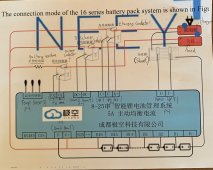
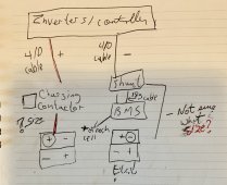
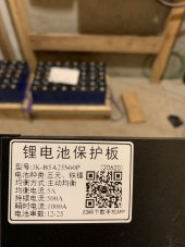
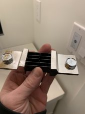
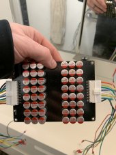
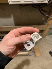
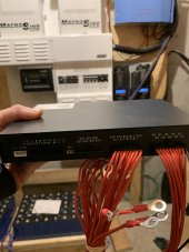
I purchased 32 - 280ah 3.2 v CATL batteries. Doing two strings in parallel of 16 batteries in series. Found out I need a BMS for each string of 16. Purchase two JK B5A25SA60P and two 16s equalizers (pic attached). The BMS has a shunt (pic attached). To attach my battery cables I purchased lugs to go 4/0 cable to 1/4” terminals (pic attached).
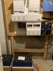
For my current system I have 2 Magnum Energy MS4448PAE inverters and two midnite solar classic 150 charge controllers.
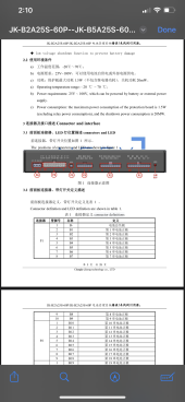
Where to begin?!?! - an English manual would be awesome. JK has not provided. Any links they’ve shared and all I see or can find is a Chinese manual.
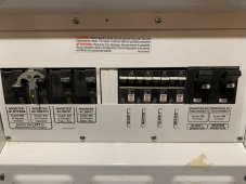
I live in Saskatoon Sk Canada. Did not intend to trail blaze this one on my own. Happy to pay someone who can draw me an install diagram that applies to my hardware. My magnum energy panel has some built in breakers for the current battery bank so I want to avoid redundancy.
Does anyone have any experience with these inverters/charge controller and this specific BMS doing a lifepo4 upgrade?
Again I apologize for the ignorance and very much appreciate any help!!! This my first forum post ever.
Desperate and grateful,
Luke
Anything really (preferably a wiring diagram in English). I’ve watched several videos from Andy (offfrid garage) by necessity and have learned very little as nothing seems to apply to my situation. Thanks in advance!! Here’s what I have:
I purchased 32 - 280ah 3.2 v CATL batteries. Doing two strings in parallel of 16 batteries in series. Found out I need a BMS for each string of 16. Purchase two JK B5A25SA60P and two 16s equalizers (pic attached). The BMS has a shunt (pic attached). To attach my battery cables I purchased lugs to go 4/0 cable to 1/4” terminals (pic attached).
For my current system I have 2 Magnum Energy MS4448PAE inverters and two midnite solar classic 150 charge controllers.
Where to begin?!?! - an English manual would be awesome. JK has not provided. Any links they’ve shared and all I see or can find is a Chinese manual.
I live in Saskatoon Sk Canada. Did not intend to trail blaze this one on my own. Happy to pay someone who can draw me an install diagram that applies to my hardware. My magnum energy panel has some built in breakers for the current battery bank so I want to avoid redundancy.
Does anyone have any experience with these inverters/charge controller and this specific BMS doing a lifepo4 upgrade?
Again I apologize for the ignorance and very much appreciate any help!!! This my first forum post ever.
Desperate and grateful,
Luke
Attachments
-
 526194D8-C965-4BBD-A2AA-7E15DCDABC23.jpeg159.1 KB · Views: 33
 -
 19A56AF6-C57F-4114-AAEE-B37367AA32F8.jpeg128 KB · Views: 32
 -
 E07522D0-DFC0-4BBF-857A-C8FDE6E43F6A.jpeg74.3 KB · Views: 33
 -
 B358490C-0660-4D0E-8CE1-E92F980DA951.jpeg131.4 KB · Views: 36
 -
 50CE31B2-EED8-4B4C-852C-D734630C7347.jpeg94.7 KB · Views: 39
 -
 86FEC5D2-75B8-4B9B-9578-274785D5554E.jpeg121.5 KB · Views: 38
 -
 BF2132DA-40D1-4D65-B14A-953059EFBCDD.jpeg179 KB · Views: 39
 . I suspected this was the case but I’m glad you guys have removed all doubt.