


You are using an out of date browser. It may not display this or other websites correctly.
You should upgrade or use an alternative browser.
You should upgrade or use an alternative browser.
Muller Industries - BMS for Valence U27-12XP
- Thread starter tab783
- Start date
Yes if you go back just a little bit you'll see I spoke in depth about itSeen this? BMS master for U27-12XP
https://www.thunderstruck-ev.com/valence-battery-bms.html
Perrybuilds
New Member
- Joined
- Sep 30, 2019
- Messages
- 16
I gave them a call today and found out some details. This BMS is good for some minor things but the problem for anyone looking to put modules in series is that this bms will not command the modules 12V resistors to activate in order to keep series modules in balance with each other. It will open up communication to the batteries which will enable the batteries to balance their internal cell blocks to other internal cell blocks within the same module. And it will also control separate relays to disconnect the battery from the charger or from the load based on cell voltage for high voltage and low voltage protection. For a system with any modules in series this will end up causing imbalances and more and more voltage out of tolerance disconnects over time unless you also get an additional aftermarket module to module balancer. So this BMS will do good for anyone who gets an additional aftermarket module 2 module balencer and has 4 modules in series parallel at 24 volts or anyone who has four modules in series for a 48 volt system. If you have eight batteries (12v modules) or more it would be cost-effective to invest in the Mueller industries BMS.
That being said you should know that this BMS is literally fresh on the market and still has room for improvement. They are currently working on adding a can bus communication in addition to the rs-485 connector it's already utilizing to communicate to the batteries. I would not rule out an upgrade in the future enabling module to module balancing because that is absolutely vital for them to sell these in large numbers.
Thanks for sharing. I contacted them a couple weeks ago when I found the unit and requested some info. They seemed helpful and I ordered it.
Luckily I'm running my valence in parallel (12v) so I think I'll be okay... I wanted the muller unit, but not at that price point.
I'm hoping I can successfully use it with my victron hardware using the inputs for disconnect.
Here is a new version of the Arduino code which corrects visual discomfort of the gauge on the nextion screen.
Does anyone here know a way to activate multiple valence batteries simultaneously and without using an external BMS.
I'm looking for myself too. The first who finds does not gain the right to share. Have a good day .
Does anyone here know a way to activate multiple valence batteries simultaneously and without using an external BMS.
I'm looking for myself too. The first who finds does not gain the right to share. Have a good day .
Attachments

I gave them a call today and found out some details. This BMS is good for some minor things but the problem for anyone looking to put modules in series is that this bms will not command the modules 12V resistors to activate in order to keep series modules in balance with each other. It will open up communication to the batteries which will enable the batteries to balance their internal cell blocks to other internal cell blocks within the same module. And it will also control separate relays to disconnect the battery from the charger or from the load based on cell voltage for high voltage and low voltage protection. For a system with any modules in series this will end up causing imbalances and more and more voltage out of tolerance disconnects over time unless you also get an additional aftermarket module to module balancer. So this BMS will do good for anyone who gets an additional aftermarket module 2 module balencer and has 4 modules in series parallel at 24 volts or anyone who has four modules in series for a 48 volt system. If you have eight batteries (12v modules) or more it would be cost-effective to invest in the Mueller industries BMS.
That being said you should know that this BMS is literally fresh on the market and still has room for improvement. They are currently working on adding a can bus communication in addition to the rs-485 connector it's already utilizing to communicate to the batteries. I would not rule out an upgrade in the future enabling module to module balancing because that is absolutely vital for them to sell these in large numbers.
Yea I had a long talk with them too and discovered all the points you outlined above. They didn't sound like they were going to add the inter module balancing feature anytime soon, but on my follow-up call a day or so ago they told me they were adding more features to the BMS software. Since the inter module balancing is very important and it seems others might be requesting it, lets see what develops. I do like the fact it keeps the batteries internal BMS systems active which does the intra cell balancing. This at least lets me have my small setup keep the batteries internally balanced without having to have a PC permanently connected running the Valence diag software to accomplish this. Since I am only running at this time a 2 battery system, an inexpensive external battery balancer will keep the batteries balanced until Thunderstruck adds the inter module balancing feature.
cheezemanrich
New Member
I gave them a call today and found out some details. This BMS is good for some minor things but the problem for anyone looking to put modules in series is that this bms will not command the modules 12V resistors to activate in order to keep series modules in balance with each other. It will open up communication to the batteries which will enable the batteries to balance their internal cell blocks to other internal cell blocks within the same module. And it will also control separate relays to disconnect the battery from the charger or from the load based on cell voltage for high voltage and low voltage protection. For a system with any modules in series this will end up causing imbalances and more and more voltage out of tolerance disconnects over time unless you also get an additional aftermarket module to module balancer. So this BMS will do good for anyone who gets an additional aftermarket module 2 module balencer and has 4 modules in series parallel at 24 volts or anyone who has four modules in series for a 48 volt system. If you have eight batteries (12v modules) or more it would be cost-effective to invest in the Mueller industries BMS.
That being said you should know that this BMS is literally fresh on the market and still has room for improvement. They are currently working on adding a can bus communication in addition to the rs-485 connector it's already utilizing to communicate to the batteries. I would not rule out an upgrade in the future enabling module to module balancing because that is absolutely vital for them to sell these in large numbers.
The 12V resistors are not needed because when the batteries are connected in series the 4 internal balancing resistors will automatically engage on each cell. If all 4 cells are high, all 4 balancer resistors will be active. This is the same as in the Valence BMS control system.
Richard
you are incorrect. I tested with a thermal imaging camera. I activated the cell balancing board by the required communication with something and 5 volts supplied to the batteries internal board from external power supply. I pushed the cells over 4 volts each. As long as they remain balanced the resistors did not heat up. Unless thier balancer unit is somehow controlling the activation of the cell block resistor you shouldn't put them in series. It seems like it would be smart to use the cell block resistors in this way as well but valence does not have it programed that way. and honestly when I'm using the correct resistors for the job they have a hard time keeping up as it is. I would hate to rely on the cell block balancers which are actually smaller and in lesser numbers.The 12V resistors are not needed because when the batteries are connected in series the 4 internal balancing resistors will automatically engage on each cell. If all 4 cells are high, all 4 balancer resistors will be active. This is the same as in the Valence BMS control system.
Richard
Last edited:
cheezemanrich
New Member
There must be some differences in our setups or batteries/BMS firmware. I have 4x U27-12XP in series (48V system). As long as I treat my batteries well by not putting in or pulling out a huge amount of current (within specs) they stay very well balanced. The balancer internal to my batteries is always active, even without an external 5v. I verified this by opening the case and measuring the cells when nearing full charge when I didn't have the Valence SW yet. With the Valence SW, I can also see the balancing working properly. The only time I see a possible issue is when I over discharge the batteries which I don't do any more. I don't discharge below 20% as at about 15% the cells start to unbalance and at about 8% they get pretty far out of whack. I also set my charge controller to 55.6 and disable temp compensation. This keeps things in check and gets me to about 95% state of charge. My charge rate is only about 9A max on a really good day so this could also be a factor as it's a very low rate. Been running like this for about a year now without any problems.
There must be some differences in our setups or batteries/BMS firmware. I have 4x U27-12XP in series (48V system). As long as I treat my batteries well by not putting in or pulling out a huge amount of current (within specs) they stay very well balanced. The balancer internal to my batteries is always active, even without an external 5v. I verified this by opening the case and measuring the cells when nearing full charge when I didn't have the Valence SW yet. With the Valence SW, I can also see the balancing working properly. The only time I see a possible issue is when I over discharge the batteries which I don't do any more. I don't discharge below 20% as at about 15% the cells start to unbalance and at about 8% they get pretty far out of whack. I also set my charge controller to 55.6 and disable temp compensation. This keeps things in check and gets me to about 95% state of charge. My charge rate is only about 9A max on a really good day so this could also be a factor as it's a very low rate. Been running like this for about a year now without any problems.
Sounds like you need to do more testing to prove to yourself what's happening. Try these tests and let us know the results.
It's possible yours are working well because there already balanced well.
Checking cell voltage with a multimeter while having no laptop hooked up is the only way to see the voltage untampered. as soon as you hook up the laptop it activates the balancing board which only balances cell blocks between each other. With laptop not connected & while manually checking all cell voltages to make sure none go over 3.8 remove the side covers and try 58.4v. You'll want to do this in stages in starting from the voltage you have previously set and increasing by 0.3v at a time. With your finger monitor the tiny groups of resistors on the top left and bottom left of the board. If you don't feel any warmth and your voltage starts separating by more than .05 volts between cells You're not balancing.
Resistors on the top left are for cells. Resistors on the bottom left are for the entire battery.
Then do the experiments again with the laptop connected and you'll notice the higher voltage cells will cause the resistors to get warm. Slowly and safely raise the voltage to 13.9v per battery & then hold it there for quite a while while the resistor stay warm and I mean quite a while like as in days. Then raise the voltage to 14.1 volts (or up to 14.8v) per battery and hold it there until the resistors become cold this may take as much as 200 hours. And I mean actual hours don't count the night times when the solar is off. I have to warn you though with 4 in series you're going to realize that you're not series balancing and you'll end up noticing you are severely limited by the fullest battery and you won't be able to raise all the batteries high enough to complete the 200 hour balance. You need a proper u-BMS or 4 channel 12 volt battery balancer like I posted in one of the first three posts. Continuing like you are you're having a battery drift. The reason some of my batteries took 200 hours to balance is because they were allowed to go out of balance for many years. Now that I've balanced them I find them staying in balance much easier.
Last edited:
Many thanks for sharing this information.
I have a few questions for you.
Please contact me at : mongrenier@msn.com
I sent you an email, haven't seen a reply yet.
")
I'm just getting started with solar and learning what I can so excuse the simple question. I have one of these U27-12xp batteries on my travel trailer being fed by a 100W panel (which I plan to expand).
The question is, am I OK using this single battery without the external BMS? What if I add a 2nd parallel? If I'm not, would that Thunderstruck BMS be sufficient for my needs?
Thank you for your advice.
The question is, am I OK using this single battery without the external BMS? What if I add a 2nd parallel? If I'm not, would that Thunderstruck BMS be sufficient for my needs?
Thank you for your advice.
I'm just getting started with solar and learning what I can so excuse the simple question. I have one of these U27-12xp batteries on my travel trailer being fed by a 100W panel (which I plan to expand).
The question is, am I OK using this single battery without the external BMS? What if I add a 2nd parallel? If I'm not, would that Thunderstruck BMS be sufficient for my needs?
No you won't be okay without a BMS. And yes the thunderstruck BMS would be sufficient for a single battery or any number in parallel but you need to make sure you have a contactor hooked to it so that the BMS can disconnect your battery in case you accidentally try and over discharge the batteries. over discharging is particularly easy in an RV because it uses 12 volts for all kinds of stuff. not like a traditional person would have an inverter hooked to the battery and the inverter would shut down when the battery got low. And make sure you have a charge controller between the panels and the battery. Search this website for valence super thread. It has lots of information
Thank you for your advice.
Thank you! I do have a 30A charge controller. There also is a 1000W inverter. But I get what you're saying about the DC connected stuff. I've already camped 3 days without exhausting the battery (went down to 12.7V) and that was on cloudy days. I've also obtained a 2000w propane generator just in case solar doesn't give me enough recharge and plan to increase panels to 300W. Goal is to be able to dry camp for 5 days. Plan was to hit lots of music fests this year. F Covid... So this year it's more state parks instead and time to work out my energy system!
Heads up the propane refrigerator in my RV was computer controlled & the computer system took more power than a standard electric household refrigerator. I'd recommend putting a meter on everything so you know how much each thing takes so you can make the correct decisions for your system. I'd recommend 350 to 450 watts of panels per each U27-12XP.Thank you! I do have a 30A charge controller. There also is a 1000W inverter. But I get what you're saying about the DC connected stuff. I've already camped 3 days without exhausting the battery (went down to 12.7V) and that was on cloudy days. I've also obtained a 2000w propane generator just in case solar doesn't give me enough recharge and plan to increase panels to 300W. Goal is to be able to dry camp for 5 days. Plan was to hit lots of music fests this year. F Covid... So this year it's more state parks instead and time to work out my energy system!
I read the other thread, and a few other things about contactors. The Thunderstruck BMS says that it protects from low voltage. Doesnt that mean it will shut off the battery when voltage gets too low? Why would I also need the contactor? And if I do, can you point me to an example of one? . I'm pulling up aircraft related stuff while looking for one.
The batteries cannot be shut off internally. The thunderstruck will need to be wired to and will open and close a relay "contactor" in order to disconnect the battery Bank when it deems necessary. https://www.ebay.com/sch/i.html?_nkw=ev200&_trksid=p2380057.m4084.l1313.TR11.TRC1.A0.H0.Xev200.TRS0I read the other thread, and a few other things about contactors. The Thunderstruck BMS says that it protects from low voltage. Doesnt that mean it will shut off the battery when voltage gets too low? Why would I also need the contactor? And if I do, can you point me to an example of one? . I'm pulling up aircraft related stuff while looking for one.
When you're shopping make sure they have the economizer "pwm" board included, The contactors I provide do have this board and it greatly reduces their power consumption and also widens there control voltage tolerance.
Last edited:
Youve explained this all very well. I've spent all morning reading your other posta and other info and believe I understand all.
One thing I'm lost on though, the Thunderstruck wiring diagram indicates that the LV contactor should be wired in line with the negative returning to the battery from the load. But there is no negative connection to my battery other than the grounding wire to the trailer A frame, and another from the solar controller. Not sure where I would install that LV contactor. Does it go between the battery negative terminal and the frame ground? Or do I need to find where all the DC negative connection are terminated and wire it in there? Or am I completely misunderstanding something?
Thank you again!
remember your goal with the contactor is to be able to disconnect the battery. Removing either wire will accomplish this. So to answer your question. Yes you are correct in your 1st idea of where to put the contactor between the battery negative and the body ground.Youve explained this all very well. I've spent all morning reading your other posta and other info and believe I understand all.
One thing I'm lost on though, the Thunderstruck wiring diagram indicates that the LV contactor should be wired in line with the negative returning to the battery from the load. But there is no negative connection to my battery other than the grounding wire to the trailer A frame, and another from the solar controller. Not sure where I would install that LV contactor. Does it go between the battery negative terminal and the frame ground? Or do I need to find where all the DC negative connection are terminated and wire it in there? Or am I completely misunderstanding something?
Thank you again!
Where did you send it? Can you please send it to kamhuss66@yahoo.com ? ThanksPlease can U send me the software.. thanks
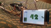
Did u connect any relays or voltage divider? Could u please post a picture of the full circuit? Would u mind sharing the code with me? ThanksHi,Here a gauge designed on arduino and nextion to display the SoC battery given by the U bms Valence in pin 2 connector 3.
kamhuss66@yahoo.comGive an email address for sharing.
remember your goal with the contactor is to be able to disconnect the battery. Removing either wire will accomplish this. So to answer your question. Yes you are correct in your 1st idea of where to put the contactor between the battery negative and the body ground.
So I got the Thunderstruck and a contactor, but their wiring diagram in the manual appears to include a separate 12v source for the BMS and Contactor from the Valence battery. Can I use the Valence itself as the 12v source? Is my attached wiring diagram correct?
Thank you!

yes you can use the valence battery as the 12-volt source.So I got the Thunderstruck and a contactor, but their wiring diagram in the manual appears to include a separate 12v source for the BMS and Contactor from the Valence battery. Can I use the Valence itself as the 12v source? Is my attached wiring diagram correct?
Thank you! View attachment 16019
And if you wanted to get super protective I would set it up so that if the BMS where to disconnect the battery Bank because of low voltage it would even kill power to itself so that way it's own power draw would never run the batteries down further. I would put a momentary switch as a bypass switch around to inject power into wake up the BMS. It's just a theory though I've never used the thunderstruck myself.
yes you can use the valence battery as the 12-volt source.
And if you wanted to get super protective I would set it up so that if the BMS where to disconnect the battery Bank because of low voltage it would even kill power to itself so that way it's own power draw would never run the batteries down further. I would put a momentary switch as a bypass switch around to inject power into wake up the BMS. It's just a theory though I've never used the thunderstruck myself.
Thanks! I considered doing that, but the only time this should possibly come into play is when I'm in the trailer using electric so I'm sure I'll be aware if cut off occurs. When I'm not using the trailer it's parked outside my dining room in full sun most of the day and minimal draw on the battery. During storage it will be disconnected. I was more concerned with internal balancing of the valence but integrating the LLS just in case.
Thanks again for your help!
Similar threads
- Replies
- 2
- Views
- 452
- Replies
- 1
- Views
- 456