diy solar

diy solar

BMSes for use at 96v or higher (EVs, boats or similar)

Joined
Jul 20, 2020
Messages
79
Location
lake county, california
Soon I'll be into a project that will require voltages greater than the usual 48v seen in solar power. (It is an "extreme" case involving an old EV that ran lead batteries.)

The plan was to get LiFePO4 cells to make up a 30S pack for 96v "nominal" and 109v max. Maybe 100AH to start. Source TBD. (If you have some extra, sell them to me!) With the possibility of going to 32S or 35S later if necessary. There are plenty (too many) types of BMSes for 12v to 48v, but above 48v things get much scarcer and more costly. A few BMSes for 24S can be found on Ali Express but that's not enough voltage.

The Orion BMS has been repeatedly recommended to me. You realistically can't assemble an Orion for 96v, on the LOW end of their operating range, without spending upwards of $1200, not counting the cells and hardware. Plus it wants to talk to the charger over CANBUS so you "have to" get a charger capable of taking orders from the Orion. It does have the advantage of being able to control a contactor for safety shutoff. There are a few other BMS devices, but they tend to be simple cell monitors that do no balancing.

The Elithion company makes commercial EV BMSes (won't sell to me, "OEMs only", "We are unable to accept new customers due to the chip shortage") but maintain a list of EV BMSes for hobbyists on their website. Unfortunately a large number of the devices are now defunct/unavailable. Despite EV conversions being an "exploding" field, some resources are actually declining. The few that are readily available are either just monitors (the Thunderstruck/Dilithium, which isn't in that list) or are costly and complex to use (Orion, Elithion, Batrium). Don't mention the AEM EV BMS: despite still being advertised by dealers it's been discontinued.

Anyone using old Tesla or Nissan Leaf power components etc. in a conversion ends up buying one of those costly EV BMSes because the BMS in the original vehicle battery pack is "undocumented" and needs to talk to a CANBUS controller. Tesla is especially notorious for being secretive about all this. See the (few) YouTubers who did (recent) EV conversions. Warning: loads of the YT videos on this subject are posted by conversion shops trolling for business. They have zero interest in helping true DIYers.

There has been talk about the legal-liability situation being "dire"--inevitably quite a few total fools tried to use Li-ion packs from old Tesla Model S cars or homemade "powerwalls" made of 18650s, who then hooked them up incorrectly, and started a fire. Or two or three.

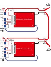
Yes I've seen the threads on this forum about people putting two 48v lithium batteries in series, or asking if it would work. It's just frustrating that we have this massive jump in BMS prices above 48v, as well as a greater scarcity. The electronics in all BMSs are apparently very similar, and I don't buy this stuff about higher voltage MOSFETs costing exponentially more or whatever. But I'd prefer not to buy two 48v BMSes and "play around", if possible.

Any serious suggestions would be appreciated.
 
Try REC BMS. I use them, they are vehicle quality units.
Referring to this?
I went thru the process, and it ended up costing more than $2000 with two slave units and cables. That's more than the equivalent Orion. Let's keep that as a backup possibility.
 
Referring to this?
I went thru the process, and it ended up costing more than $2000 with two slave units and cables. That's more than the equivalent Orion. Let's keep that as a backup possibility.

Keep in mind that the balance current on an Orion is only 200ma.. Rec is 1300ma.

If you install a BMS with an inadequate balance current, it can cause problems.

Orion is a good product and I doubt your going to find anything else out there (Besides the REC) that is capable of handling 100 volts..
 
perhaps a stupid idea, but can you not just place them in series?
2 x S16 BMS make S32??

I know i probably am missing some major shortcomings, yet, i fail to see where.
why should it not work???

If one can use 2 x S4 to make an S8, or 4 x S4 to make an S16....
 
perhaps a stupid idea, but can you not just place them in series?
2 x S16 BMS make S32??
Threads on this forum (some of them very long and ranty) have beaten on that very subject. Apparently "you shouldn't do that" because if one BMS shuts down, it will have the full 96v of both packs across its internal MOSFET switch. If cheap BMSes had facilities to shut each other off in series connection, like logic-in/out pins to force systems shutdown, this would be less of a problem; have not seen that in any commercial products other than the costly ones made for EV batteries.

I can easily believe this could be a problem for cheaper BMSes and there are possible solutions using additional voltage monitors or current leakage detectors, and contactors. I've yet to see anyone actually try it and report back that it worked or not. Just a lot of blah blah blah.

Have a look.


This Heltec thing looks interesting, but weird. Claims to do 300mA balancing. Makes me think of someone's hobby project that was then produced in quantity. It is sold on Ali Express.
 
Last edited:
I talked with Hankzor BMS store and apparently next month the JK will have that communication line (or such), to tell the other units to also shutdown.
They will support series soon.

You are right, now if there is an error, one or both BMS are fried.

Risk assessment, what are your plans?
If you stay in the 10-90 SOC range, not much risk.

For top balance there are tons of external active balancer that should prevent the cells for ever getting too high. 1,2,5, even 10A...

In reality there is only the occasional failed cell that will trigger one BMS and fry the other ones in the process.

Even without the new JK ... Not that huge problem.

My friend had 4*S4 left over (100A Daly) and made them in an S16.. works (for now, already about a year, low intensity useage)

But .. will there be influence in the cells? / Battery packs?
Do they care?

Say 8* S8.. would be 8* 24v BMS or 4* 48v. (+200v setup)
Is it only the BMS that is at risk, or are there other "forces" at play?

I received a warning from my suplier not to go beyond 48v, mainly because it's not tested and not adviced.

Just curious if there are technically reason why someone should not do it.
besides a cascading error if one BMS does what it should do.. protect over (dis)charge if the individual cells.

I always see an BMS as an airbag in a car. It's best it never needs to be activated to do its thing.
and especially low intensity use like solar, it never should need to be active, stopping the charge or the discharge, unless there is a serious problem.
 
What exactly do you wish this BMS to do? Does it need active balancing or just voltage cut offs? and what kind f communications do you need if any. I dont have a solution for you but am more curious as to what your exact needs are in this situation
 
In my possible situation, 3 phase inverter that needs minimal 160v battery. Why? Because it has 200A passthrough and my friend needs this.
Alternative ("low voltage") would be 3* 12kw units. Not that he needs 12kw, but they have 100A passthrough each
(12kw Deye, Victron (8kw) would also be possible, except the 8kw = +$4500 and the Deye+$2250)

The 3 phase (30A) is a nice match, if it would just work with 48v :)...

Most others have no passthrough or as 3 phase like 45A, that's 15A per phase.
He needs minimal 50A, preferred +60A
As there are spikes per phase of +11.000 watt.

And yes, sure he can stack 6 or better 9 units 3*3 of 5.5 (or so) KW..
Parallel and series...
Lots of points of failure.
And usually only on paper, the Chinese didn't test that heavy usage.

A few test we did was $$$ and lots of failure. Those where sold again.

So that is the deal for the 200v battery.
10 kWh BYD we can get for $1900
(S16) including BMS and Stainless steel casing.

1000014946.jpg

They never done in series, and their supplier adviced them against it.

I know normal pricing is roughly $4, 4.500 per 5 kWh. Huawei, Tesla, even BYD power walls...

So there are bound to be some unexpected surprise when you get 10kw for $1900.

Not for normal solar daily light cycle say 60-70% or so...

But high (dis)charge probably will give more imbalance. (They are equipped with the 200A 2A JK BMS active balancer)

I'm using 3 sets.
Back then they where 260A, and S8.. so 6 make 13.3, close to 40 kWh.
Bought them after my fire.
That was June/August 2021.
Steady as a rock :)

I guess my friend is better off by staying at the 48v.

Ot would only need to work as "airbag".. cell monitor and yes.. if things go wrong, stop.

As the units busbars are laser welded.
Stoping should be during a cell problem. That can't be replaced.

So...
If it does trigger.. it would be during accident phase, and the ones that cascade fry will be collateral damage.
As long as the other batteries are safe.

So that is the question...
Is there any reason, besides probably shady background of the cells, why higher voltage series are a problem?

*I expect the cells to be from golf carts, busses or similar and at their 80%, or perhaps did not pass the BYD QA test for EV (high charge / discharge)
For light solar... They are good :)
 
I use Batrium for my RV. It can handle a lot of cells - don’t remember but I remember it can handle enough for 150v battery.

A Batrium Core and two K-9’s and fuses, expansion board, and shunt plus shipping you will be about at the $1,000 mark. Probably 1250 by the time you get everything else - contactor, Class T, etc.

But then you have a good bms - will not need can-bus - but it has it if you want it.

You are looking at a 32 cells - the bms will be the “cheap” part…
 
Yeah.. BMS is in my opinion always the cheap part.
If you can't afford it, don't buy the batteries.

Like with a motorcycle. You should (after obtaining your license) first buy a good helmet and suit, and from the money left over, find yourself a suitable motorcycle :)
-> in that order. Helmet, suit, wheels.

And I know there are tons of people doing it differently, does not change that it is be best advice and approach.

I had my batteries a few months without BMS (not the BYD, Eve's)

Start pandemic, transport was on its ass and my Daly died after 3 months.
The new smart Daly didn't even start (early adaptor luck) and living off grid..
It's the choice of no electricity or..
No BMS.

A human can be BMS it just takes up a few hours every day and conservative (dis)charge settings...
Even then, you probably will miss some almost critical voltages ..
Not good.

Thailand had a funny way during pandemic...
They desinfected parcels with alcohol.
Spraying it all around...
Guess what happens to the address labels, especially the ink that is...

2/3 of the parcels from china got lost.
aliX even froze my 15 year old account because I claimed too much parcels not arriving.. haha..
After a few months it probably became clear to them that I was just one of the first in the large wave of lost parcels...
It suddenly worked again..
Credit card covered some of the losses, but also their had their limits.

Anyways....
Focus...
Lol.

There are a few BMS already out there, $500-1000 range (so 125-250 per S16) that are capable.
And soon the JK BMS. (Who costs about $150)

I'm more worried about the effects to the individual cells when it goes in series to +48v, up to 200v.
 
What exactly do you wish this BMS to do? Does it need active balancing or just voltage cut offs? and what kind f communications do you need if any.
Voltage monitoring and some kind of balancing would be good. Don't really care about communications, though that is up to whatever battery charger we end up with. Battery chargers for EVs are another costly and weird area. You can easily get a 48v 1kW charger for about $250 but 96v or more, the price multiplies. This is a "cheap" one.
Risk assessment, what are your plans?
This is for a low-speed vehicle. It will not be raced or foot-floored on a freeway but a reliable 50 mph cruise would be excellent. Slow charging on 120v is adequate since it won't be a large battery.
 
perhaps a stupid idea, but can you not just place them in series?
2 x S16 BMS make S32??

I know i probably am missing some major shortcomings, yet, i fail to see where.
why should it not work???

The shortcoming as noted is full voltage across FETs of one BMS.

I think a suitable bypass diode (big honking 200A diode with heatsink) per BMS fixes the issue.

I've mused about whether I could put two 48V batteries in series, center likely grounded, for two Sunny Islands.
Probably not, since master monitors battery and tells slave what to do.
 
before someone mentions this: I've seen it, and 120A isn't enough current, so thanks but no


Yes I asked Daly already. They can make something for this, but have a minimum order of 25 pieces. The common 16S or 24S 300A BMS offered on various websites is the largest they make for direct sales.

I think a suitable bypass diode (big honking 200A diode with heatsink) per BMS fixes the issue.
Okay, maybe--do you know of anyone who has tried it?
 
Last edited:
Okay, maybe--do you know of anyone who has tried it?

<Diode bypass to protect series-connected BMS>

Nope.
Nor have I in the physical world, I haven't even used a BMS.
But I thought about it in my head. Could put it in LTSpice if I cared.

The deal is, if you have several voltage sources in series (e.g. PV cells/panels, or batteries), if one can't produce enough current to keep up with the load, current tries to force through it. The weak one becomes a resistor passing some current, and voltage on its positive side drops below its negative side. Bypass diodes in a PV array protect against that.

If a switch/breaker/relay/BMS Mosfet in series with voltage sources goes open circuit, the load pulls it down, past the potential on the other side of the switch/MOSFET, all the way to negative most potential of the voltage sources. So 4x 12V batteries in series puts out 48V, but if the one on top opens BMS, it's positive side goes to zero, -36V relative to negative side of the top battery, -48V relative to positive side of top battery. That's 48V across the MOSFET. Same would occur for any battery in series. Positive terminal of second battery is at +24V, and BMS Mosfet would get driven to -24V, seeing 48V across it.

If you had a bypass diode able to handle the current, positive side of BMS would go to a diode drop (about 2V) below negative side of BMS.

Bypass diodes in some PV panels fail under full current. Make sure BMS bypass diode is properly heatsinked, or shut off load.

Other concern would be voltage that other signals can withstand. For instance, EMI filters on data ports might have capacitors of limited voltage. Ethernet is transformer isolated, and I think has no capacitors on external nets. But USB would be bad news (unless connected to an isolator, and it didn't have any such capacitors.)
 
If a switch/breaker/relay/BMS Mosfet in series with voltage sources goes open circuit, the load pulls it down, past the potential on the other side of the switch/MOSFET, all the way to negative most potential of the voltage sources. So 4x 12V batteries in series puts out 48V, but if the one on top opens BMS, it's positive side goes to zero, -36V relative to negative side of the top battery, -48V relative to positive side of top battery. That's 48V across the MOSFET. Same would occur for any battery in series. Positive terminal of second battery is at +24V, and BMS Mosfet would get driven to -24V, seeing 48V across it.

Okay, aside from communications, ground isolation and other issues, here's two 48v packs with typical BMSes attached.
Where would you put the protection diodes? I'm thinking you are talking about putting them between P- and B-.
 

Attachments

  • bms-wiring.jpeg
    bms-wiring.jpeg
    71.1 KB · Views: 6
Across P+ and P-, same place as external cables.
Polarity is backwards, so zero current flow (if forwards, it would short out the battery and burn up or cause BMS to disconnect for over-current.)

The diode is there to keep PV+ from being pulled far below PV-, which is what would happen if you put a load (e.g. resistor) between PV+ of top battery and PV- of bottom battery, and BMS disconnected.

It won't do anything for PV+ going excessively high, like if an MPPT SCC failed shorted and delivered Vmp or Voc of PV array to battery.
 
Just an FYI, the project was completed, using an A123 battery pack with internal BMS, and everything posted here:


The A123 pack, MCU and charger ended up being far cheaper than buying an Orion/etc BMS and separate battery cells. But except for small vehicles like this, putting lithium into an EV is ususally a big and costly job.
 
Back
Top