diy solar

diy solar

Parallel connection of battery packs and their BMSes to the inverter via CAN (not serial).

mmx01

New Member
Joined
Jun 11, 2023
Messages
9
Location
Belgium
Hi,

I am looking to connect two battery packs in parallel and would like to keep BMS communication with the inverter via CAN instead of just voltage/current. I saw that pylon is doing this via LV-HUB module where serial strings connect in parallel and their BMSes are connecting to this hub which in turn is connecting to the inverter.

Since I am an engineer I am considering building one myself :) I already built JK-BMS to Growatt CAN L52 protocol converter using and enhancing code which is already on github and it is working great.

Looking at this device I assume LV-HUB is doing the following:
  1. Each BMS battery port of LV-HUB comes with its own CAN driver and terminations on both ends. In fact it is likely implementing multiple CAN busses internally one per parallel battery module. The reason why I think so is that I have nowhere found within pylon LV CAN protocol battery ID to distinguish reply origin to 0x305 request (unless dip switches operate this at can controller level transparently to the protocol itself). Without battery ID on a shared bus there's no telling which unit sent it. Also more likely if one string would develop and issue and the other did not, the outcome should still be an alarm and battery system shutdown.
  2. Also LV-HUB is likely sending consolidated data to the inverter. I.e. with Victron you don't see individualpacks (not even strings) for such configuration but just aggregated set of data like for one large pack.
  3. Therefore I assume LV-HUB is performing calculation on numeric data like battery voltages, currents, SOC as "mean" for the entire battery module with parallel strings and for bit data like alarms as OR (boolean algebra) for of each of parallel strings.

If anyone with experience could confirm the fact that such devices basically are averiging out data across the battery banks and since each has its own BMS providing safety to cells it seems logical. Otherwise interters would be aware of multiple batteries and at least with victron they seem not to be.

Regards,
M
 
That is correct. The Pylontech to inverter CANBus protocol has no concept of different batteries. It just presents the inverter with SOC, charge / discharge demand and a current view of voltage, current for the 'battery pack' as a whole.

With batteries connected, correctly, in parallel, there should be little difference in the voltages etc. between them.
 
Thanks, I did not want to miss something out before starting experimenting. Battery packs are of course of the same cells/voltages/capacity.

I will then build a bridge system with 3x CAN transcievers:
  1. 2x downstream to pull data from batteries via 0x305 which the bridge will be managing.
  2. Data acumulation and calculation routines for mean pack data.
  3. 1x upstream to reply to inverter's 0x305 with calculated mean pack data.
Need to figure out how to manage situation when say both packs are still connected to bus bars so participating electrically, yet one of them looses CAN connection and no longer reports back to the bridge. I can easily count if we have both downstream responses in data pool cycle, if we do not then likely we just don't push anything upstream hence inverter will shutdown on can timeout altogether.

Timing within 1 sec will likely require some fine tuning. I.e. pulling downstream every 0.75sec to have data ready and since the math is easy ESP32 should manage to calculate and push out to inverter within 1 sec.
 
OK, but don't overcomplicate it ;)

AAIAA inverters don't make requests to 'pull' data. 'Remote frame' usage is uncommon in CANBus. Unlike ModBus RTU where there is a clear client-server architecture, all nodes on a CANBus are Masters. They will / should just transmit the data on the bus, which will be received by all nodes and receiving nodes can just 'listen' for the frames they are interested in.

In my implementation (DIY 14.3kWh battery pack), I use an ESP32 with MCP2515-based CANBus controller to transmit the necessary frames once a second to my Solis inverter. The frames needed are:-

Frame ID and contents..
0x351: Charge and Discharge parameters
= (max charge voltage, charge current, discharge current, discharge voltage (the latter is not used by Solis))
0x355: SOC & SOH
0x356: Current measurement of Battery Voltage, Current & Temp
0x359: Protection & Alarm flags
0x35C: Battery charge request flags (which I heard are ignored by Solis; I don't use them)
and, if you want to be Pylontech compatible, you will also need to transmit...
0x35E: Manufacturer name ("PYLON ") = ASCII "PYLON" followed by 3 spaces.

If / when I add additional battery, I will just share data from battery 2 back to battery 1 by whatever means is most appropriate (which could be CANBus on a separate CANBus network). Then use the existing CANBus connection from battery 1 to the inverter to send consolidated data back to the inverter.

Battery 1 will send data every second to the inverter anyway, if the data from battery 2 is stale by 1 second, that won't matter (not that I can see any reason for such a big delay). My system does a whole host of other stuff (handling web requests and sending MQTT packets) and the "delay" in the sending of CANBus data is never more than about 15ms late!

With batteries in parallel, the voltages and SOC of each _should_ be the same (or at least the same as far as the inverter is concerned). All the inverter cares about is what is the SOC and what are the charge and discharge requests. The charge and discharge current will be shared between batteries, so if I know that both batteries are on-line and working, the charge and discharge values will be double the number than if I had only one battery - but only if I wanted to restrict charge below the max that my inverter can use (which is 100A in my case), otherwise just one battery pack can take the whole 100A.

Here's a link to a thread / github code that does the CANBus sending of data, that I based my solution on - might be of interest to you, especially the CanBus.cpp file for driving an MCP2515.


Hope that makes sense!
 
It absolutely makes sense. Same batteries on shared bus should effectively have the same voltages/currents & SOC.

This complexity comes from wanting to see more granular data such as individual alarms from each of BMS (since there are two) as to current/temperature etc. for pack under its control.

Say a situation when one of the batteries on separate BMS would start failing for whatever reason triggering alarms and we drift away from alignment between the packs. Such master could then take other actions to turn on relay outside of feeding inverter with an alarm.

If I ignore all that based on my setup the simplest of the solutions would be to disconnect BMSes (CAN connections) and put smart shunt behind all batteries BMSes, do not use CAN communication with them but with smart shunt instead. Then alarms and all BMS data granularity is anyway lost and I depend only on what smart shunt provides. Which is voltage, current and SOC.

Maybe I overcomlicated this ;)
 
Last edited:
Sure. I guess it will be a design decision as to where you want to collate and represent all the granular data. In other words whether you want to present that data to the inverter or to an external control system, which could take further action.

I suspect the Growatt, like my Solis has no concept of different battery packs, so it will be unable to report which pack is in an alarm state, just that there is an alarm somewhere.

My system collects additional granular data (over and above the basic V, I and SOC values), such as cell voltages, 4 temp probes, whether the heater is on or off etc. and sends that data to an external monitoring system using MQTT messages. I don't send that data to the inverter as it will do nothing with it. Obviously YMMV :)

Using a Smart Shunt for SOC across all batteries is a good idea anyway - I will probably do that when I get more than one battery running, but would still use the cell voltage data to control the cut off at top and bottom of SOC as I do already - so a bit of a mix-and-match approach.
Exactly. My growatt even ignores BMS alarms with can comm established. I tested sending to it various fabricated alarm inputs from over temp to over power or requesting bulk charging but it does not care. When set to Li it really only cares about SOC & Vbat. I tested this via CAN but also RS485 protocol as it supports both Pylon versions. With Victron I count on better software stack though but that behavior so far comes to me as norm in the industry.

ATM I have my BMSes integrated into home assistant via esphome connect modules which also bring CAN <-> RS485 translation JK-BMS is using and heating/cooling controls I have added to keep batteries in good climate. So I do see BMS input data with home assistant down to cells etc. I also implemented redundant battery temp monitoring with 2 sensors pulled from JK-BMS via RS485 and added 2 independent NTC sensors via ADS1115 connected directly to ESP32 with standard deviation calculation to eliminate "the liar" from 4 measurements for accurate reading :) Likely also overengineered but good oppty to apply standard deviation in code to eliminate the most deviating measurement (likely result of a fault) which otherwise significantly affects averaging.

With home assistant there's option to do some of control logic there but then I prefer embedded systems. Software running on top of another software on a complex device for critical conditions poses layers of problem areas vs. running this in firmware. funny system on chip and state of charge come to the same 3 letters.

New inverter should arrive this week so I will play with it testing different scenarios for accuracy and will see if smart shunt is good enough or will it be time for another project.
 
I am moving on with the project. After playing with Victron smart shunt, it is good for SOC/V/A but it has no idea of knowing how many battery modules are active when configured in parallel. Let's say any one is cut by BMS due alarm condition and with 3 modules we reduce charging capacity by 1/3. With 2 modules we reduce it by half so it is better the rest of the system knows and won't cook the remaining modules leveraging Victron DVCC and BMS data.

We have 2 ends
> Inverter end - what do we actually tell the inverter
> Battery modules end - we talk to individual BMSes of each of parallel battery modules

I tested the protocol implementation with Victron MP2 on the inverter side and inverter reports BMS communication. Did this based on ESP32 running ESPHOME so HA integration comes native. I replicate pylontech CAN and there are good sources on github from others for this part. Uksa007 code was great starting point, it also works with Growatt as Li L52.

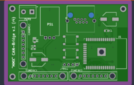
Now on multi-module end of this project, I was thinking to either have one CAN network (like normally would be the case) or a star type, where each connection from battery module BMS to the bridge becomes its own network. I went with the second option, higher cost in parts and complexity but then management of the network becomes trivial. I just look for frames with known IDs on each of MCP2515 enabling me to count how many modules are reporting alive. With this info I can dynamically calculate allowed charge current (I would not push 300A into one pack/module) and then every packet on the inverter side is recalculated based on averaged data from modules by ESP32.

Alarms are also easy since we only need to do OR operator |= for each module input and we get "the worst" alarm representation bit wise. Any alarm from any module is reported to the inverter.

I have not yet resolved point about reporting re. individual cells. I can easily find max & min voltage of any given cell from the modules but then pin pointing to which cell is that and passing this to the inverter is tricky. Cell 1-8 would not tell me which battery module would this be. I am thinking to simply adding 10 to cell number representing module. Cell 1, first cell of module 1, +10 (11) Cell 1 of module 2, +10 (21) cell 1 of module 3 etc.

These are CAN_ID 0x70 & 0x371

However I am not sure this is done like thing in commercial implementations. Do they report specific cell from a bank of battery modules to the inverter and if so, how does this show?

1711089622960.png
 
Last edited:
...I went with the second option, higher cost in parts and complexity but then management of the network becomes trivial. I just look for frames with known IDs on each of MCP2515 enabling me to count how many modules are reporting alive. With this info I can dynamically calculate allowed charge current (I would not push 300A into one pack/module) and then every packet on the inverter side is recalculated based on averaged data from modules by ESP32.
I like that concept. Presumably though you will have to look at the CAN data as well as the fact it is being sent... because if one pack triggered an error and stopped charging, it would still be sending CANBus messages - just those messages would have an alarm flag set.

I have not yet resolved point about reporting re. individual cells. I can easily find max & min voltage of any given cell from the modules but then pin pointing to which cell is that and passing this to the inverter is tricky. Cell 1-8 would not tell me which battery module would this be. I am thinking to simply adding 10 to cell number representing module. Cell 1, first cell of module 1, +10 (11) Cell 1 of module 2, +10 (21) cell 1 of module 3 etc.

These are CAN_ID 0x70 & 0x371

However I am not sure this is done like thing in commercial implementations. Do they report specific cell from a bank of battery modules to the inverter and if so, how does this show?
My Solis has no concept of individual cells - it only is aware of a "battery", the current, voltage and alarm conditions of it and, of course, SOC. It doesn't have any ability to receive or report on individual cells.

In my implementation, I just report min and max cell voltages back to MQTT based monitoring system, but that info never goes to the inverter.
 
I like that concept. Presumably though you will have to look at the CAN data as well as the fact it is being sent... because if one pack triggered an error and stopped charging, it would still be sending CANBus messages - just those messages would have an alarm flag set.

Good point, JK-BMS on alarm condition sets charging current to 0 so avg of amps / modules cnt pushed out is adjusted but not all BMSes may work like this and indeed referencing this to alarms makes sense to make it universal.

My Solis has no concept of individual cells - it only is aware of a "battery", the current, voltage and alarm conditions of it and, of course, SOC. It doesn't have any ability to receive or report on individual cells.

In my implementation, I just report min and max cell voltages back to MQTT based monitoring system, but that info never goes to the inverter.

I was looking for more info on this since newer protocol supports these additional frames. Now does the inverter needs to be aware or am I just good with HA BMS reports where I see all cells anyway... a consideration.
 
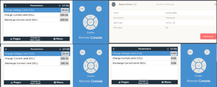
So the prototype is up. I have tested adding modules and removing modules with inverter running. Inverter recognizes this ok and adjusts settings as expected.

When all modules are disconnected but the bridge is still transmitting, it defaults to empty frames 0x00 which disables charging/discharging function. However it goes into low voltage alarm. While I would not expect to run with 0 modules, maybe some failsafe is needed.

So far looks promising.

To inverter:
2.705805 1 359 Rx d 8 00 00 00 00 03 50 4E 00 Length = 0 BitCount = 0 ID = 857
2.716075 1 355 Rx d 4 63 00 64 00 Length = 0 BitCount = 0 ID = 853
2.728082 1 356 Rx d 6 8F 0A 00 00 C8 00 Length = 0 BitCount = 0 ID = 854
2.738042 1 35c Rx d 2 C0 00 Length = 0 BitCount = 0 ID = 860
2.750118 1 351 Rx d 8 0E 01 B8 0B B8 0B DC 00 Length = 0 BitCount = 0 ID = 849
2.760135 1 70 Rx d 8 C8 00 C8 00 53 01 50 01 Length = 0 BitCount = 0 ID = 112
2.772129 1 371 Rx d 8 01 00 02 00 01 00 03 00 Length = 0 BitCount = 0 ID = 881
2.782073 1 35e Rx d 8 47 4F 4F 44 57 45 20 20 Length = 0 BitCount = 0 ID = 862

1711216751168.png


1711216300067.png
 
Back
Top