diy solar

diy solar

High Voltage DIY LiFePO4

521e6ed1757b7fcc778b456a.png.8f574fcbdd576d8a218e3f0cfb9a681b.png


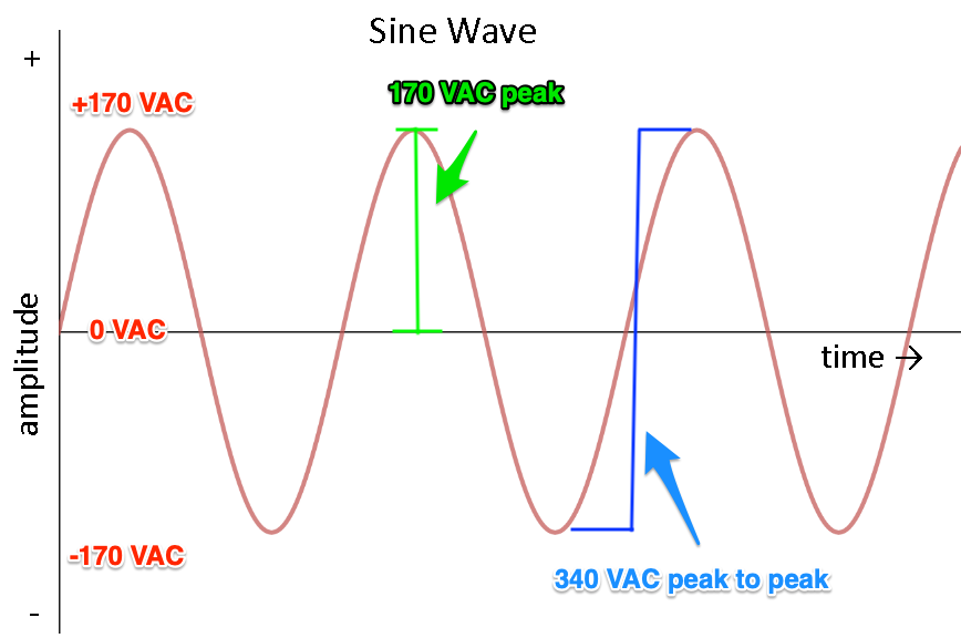
I am thinking maybe you may need somewhere around a 170 volt battery to make 120VAC but wouldn't a DC to AC inverter be simpler and more efficient if the battery DC input was high voltage from the start?

I'm not sure.
 
Using a battery to directly drive an inverter without using a low frequency isolation transformer is begging for trouble.
If the inverter blows up, it will very likely put high voltage dc direct into your household appliances killing anything that has a transformer or an induction motor. That can get rather expensive !

Nothing wrong with a high voltage inverter, but it must be a low frequency transformer type inverter.
I run thirty Lithium cells here (100v nominal) and its all a lot more efficient than the usual 48v system.
 
High dc voltage means an awful lot of battery cells.
Monitoring, protection, and balancing starts to become both complex and expensive.

Unless the power level is really high, I cannot see any advantage for off grid.
 
Nothing wrong with a high voltage inverter, but it must be a low frequency transformer type inverter.

Why not a high frequency transformer type inverter?
With battery > 340V, a buck architecture (non isolated) could make 240V. Isolated with 1:1 transformer it could as well.

Transformer isolation would be additional losses vs. non-isolated, but using HF transformer still lighter and lower cost than LF.

Unless the power level is really high, I cannot see any advantage for off grid.

Possibly an advantage in that you can add cells in series (any number), rather than adding strings in parallel.
This could also allow more watts from same inverter. Freewheeling diodes/transistors and H bridge would have to be sized for maximum AC current, but switching transistors would be sized for maximum voltage, transfer more power at same current when voltage higher.
 
I can only speak from personal experience, of once building such an inverter.
If your "buck" switching device fails shorted, you get full peak continuous dc output.

Some household appliances might survive that, many will not...... As I found out the hard way myself.

I suggest you study possible failure modes, and decide for yourself if its worth the risk.

If a typical cheap HF inverter blows up, it usually self destructs and kills the usually fairly fragile high voltage dc to dc converter supplying all the high voltage dc power.

Not so if a direct coupled HF inverter stage is powered directly from a massive virtually indestructible high voltage battery.
 
Last edited:
I agree you don't want FETs failing shorted to apply DC to AC loads.

Some MPPT SCC do that, as has been reported.
Some like the Classic are HF transformer isolated, do not do that.

There are transformerless GT PV inverters which got approved by utilities only once they were convinced that PV DC would never be applied to their transformers.

I think HF transformers can be an approach to to solve this. Architecture could look like buck, but when transistor opens, current stops flowing in driven primary winding. Instead it flows through secondary winding. Lower efficiency than buck, but still much smaller transformer than LF.

"Isolated Buck Converter (Fly-buck)"


(I would rather a cheap HF inverter was electrically isolated between battery and AC. Don't want line voltage to appear on battery terminals.)
 
How long before we see a member venture into the world of DIY HV LiFePO4 batteries?
Good question. Some time ago Jack Rickard did just that with a complete Tesla Model 3 battery and a source. I think he may have sold some before he passed away. Until the UL changes the rules that place a cieling on nominal 48 volt systems I suspect it will not be mainstream but limited to those who want to use unlisted equipment in unpermitted situations.
 
It would seem the EV parked in the garage already has this high DC voltage.
Yes but it most likely is a different voltage and a high voltage high amperage buck/boost converter and communication device to talk to your EV battery are going to be a lot more expensiver that the loss of energy from converting 240 volts AC to the battery voltage with the onboard charger that already exists in the EV.
 
Yes but it most likely is a different voltage and a high voltage high amperage buck/boost converter and communication device to talk to your EV battery are going to be a lot more expensiver that the loss of energy from converting 240 volts AC to the battery voltage with the onboard charger that already exists in the EV.
I just meant the permitting requirement for high voltage solar ESS seemed silly while the EV is parked 20 feet beside it.
 
Funny enough, I just signed up today, and I'm in the process of getting a company off the ground to do exactly this! (We're also planning to do local LiFePO4 refurbishing - taking apart marginal batteries, rescuing any still-viable cells, wiring them together into new cases with new BMS chips, and selling them for off-grid solar use)
 
The “Mike G” channel on YouTube has some good info on this. I don’t have the balls. I get nervous on the final assembly of a 16S battery and have has a few “encounters” (including accidentally learning to weld aluminum (my work surface) with a couple of 22 gauge wires).
 
Funny enough, I just signed up today, and I'm in the process of getting a company off the ground to do exactly this! (We're also planning to do local LiFePO4 refurbishing - taking apart marginal batteries, rescuing any still-viable cells, wiring them together into new cases with new BMS chips, and selling them for off-grid solar use)
Keep us posted!
 
High dc voltage means an awful lot of battery cells.
Monitoring, protection, and balancing starts to become both complex and expensive.

Unless the power level is really high, I cannot see any advantage for off grid.
I can if your using ev car batteries since all of the ones Ive seen seem to be setup for high voltage. Otherwise probably not.
 
Apparent advantages:
Higher voltage, smaller conductors, lower amperage in conductors.
Inverters internally will use lower amperage/higher voltage smaller conductors for inverting from ESS.
Fewer high voltage batteries to store the same energy as many low votage batteries.
Potential to re-use/repurpose EV batteries for solar ESS
Potential to direct charge EV from Solar ESS - will require the EV's to be ready for this.
i think all of these are secondary to the biggest advantage: bi-directional charging will require a hybrid inverter that can operate off of DC power delivered straight from an EV.

If you want the ability to use an EV as an extension of a house battery, you will either need an HV hybrid that can operate off of either an EV battery or an HV house battery or you will need a dual-DC-voltage hybrid that can operate either off of an HV battery or a 48V battery (which does not exist yet and is likely to be more expensive if it ever does).

So the vision of a modest-sized house battery to offset overnight consumption coupled with the use of an EV to supply DC power through a bidirectional charger during extended outages or extended periods of inclement weather will almost certainly be based on the use of HV house batteries…
 
Last edited:
you will need a dual-DC-voltage hybrid that can operate either off of an HV battery or a 48V battery (which does not exist yet and is likely to be more expensive if it ever does).

Actually, they do exist and they are cheap. Just not fully (or at all) integrated for bidirectional.
EV HV DC fed to PV input of cheap hybrid draws power as needed to make AC and charge 48V battery.
AC output of hybrid feeds PV battery charger.

Switch connecting HV DC enables discharge as needed.
A switch connecting AC to charger would enable fixed charge rate. Preferable would be variable charge rate using only surplus PV (which could connected to second MPPT input.)

Neither of those switches would be required if EV charger was varied according to surplus PV. For a battery inverter that does frequency shift, charger just needs to respond to frequency.

This makes EV part of your ESS. Ensuring EV is recharged for your driving needs could require additional controls.

If hybrid requires floating battery (like transformerless inverters require floating PV), that could be a problem.
 
Back
Top