


You are using an out of date browser. It may not display this or other websites correctly.
You should upgrade or use an alternative browser.
You should upgrade or use an alternative browser.
Second battery bank questions!
- Thread starter JonL
- Start date
The breaker I liked to has 3/8 studs, the same as that Blueseas disconnect.The DC breakers I’ve seen wouldn’t fit 1/0 wire size? The times I usually burn up bluesea cause a spark that makes them not work anymore, is usually when I’m experimenting.
All my lessons have been long and painful learning curves. I learned about resistors and inverters. Pre-charging ?
I was trying to hook up both battery banks the last time it happened. I’m thinking the best way would be to just disconnect the positive busbar wire linking to the battery switch, then turning on the battery switch and using a resistor before attaching the final link.
My 5000 Victron inverter requires at least 200 amp hours of battery storage in order to have it work. The Battle Born Batteries are exactly 200 A, but the SOK is only 100 amp hours since there’s only four batteries. So I need to turn on the biggest bank before I can turn on the smaller one?
Do you have a diagram of how you system
It sounds like you were connecting a new battery bank at different state of chargers in parallel. SOK near empty and Battle Born at full state of charge by closing the Blueseas switch. If this was the case you could have +100amps flowing which if making a connection with the disconnect is very easy to see the switch fail.
I have been following this for a couple days… good job 740… it has been most interesting to say the least…!The breaker I liked to has 3/8 studs, the same as that Blueseas disconnect.
Do you have a diagram of how you system
It sounds like you were connecting a new battery bank at different state of chargers in parallel. SOK near empty and Battle Born at full state of charge by closing the Blueseas switch. If this was the case you could have +100amps flowing which if making a connection with the disconnect is very easy to see the switch fail.
Something like that, but it happened after I disconnected the SOK battery bank? I knew enough to make my settings on the shunt. I just didn’t understand the two charge differences, battleborn being 56.8, and SOK being 55.2.The breaker I liked to has 3/8 studs, the same as that Blueseas disconnect.
Do you have a diagram of how you system
It sounds like you were connecting a new battery bank at different state of chargers in parallel. SOK near empty and Battle Born at full state of charge by closing the Blueseas switch. If this was the case you could have +100amps flowing which if making a connection with the disconnect is very easy to see the switch fail.
I’ll probably split the difference and make it 56. Hopefully that won’t be an issue.
In the past, I’ve had problems grounding, only because I now know it takes about two years for an electrician to fully understand it. Although I realize now that the inverter can be set at the place you buy it and that it’s either open or closed.
Learning this game late in life, at 66 it’s not easy to understand all the stuff. And I’ve never been good at math. ?
P.S. also, on the shunt one battery bank has 200 amp hours and the SOK has 100 amp hours. I set each shut differently, so I’m not sure if that could be an issue?
Last edited:
So you have smart shunt for each battery bank and it seems like you’re stating each shunt is reporting a different voltage. Is that different voltage when they are both connected together? Or when they are disconnected?
What brand smart shunt?
What brand smart shunt?
Each one is a different voltage when connected, but only on the shunt! I’m going to try to split the difference at 56. Victron is the shunt I go with, as my charge controllers are Victron and my inverter also.So you have smart shunt for each battery bank and it seems like you’re stating each shunt is reporting a different voltage. Is that different voltage when they are both connected together? Or when they are disconnected?
What brand smart shunt?
At the time I started building my system, server rack batteries were just coming out.
Hmmmm
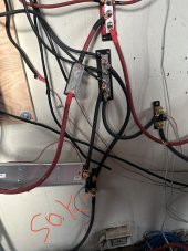
You verify the shunt voltage readings to the battery terminal voltages? I wonder if you have a poor connection or two causing the voltage discrepancies.
Can you snag a picture of the shunt voltage sense leads and how they are connected differently?
You verify the shunt voltage readings to the battery terminal voltages? I wonder if you have a poor connection or two causing the voltage discrepancies.
Can you snag a picture of the shunt voltage sense leads and how they are connected differently?
He has 12v batteries, 12v batteries that can be configured as 48v batteries.
Yes, but SOK also sells a rack mount 48v battery.
Remember, the positive wire going to the battleborn is temporary until I can get a new switch. As far as the connections go, I just tighten them down by hand. I also bought an attachment to my phone for heat sensing. Still learning how to use this thing. ?Hmmmm
You verify the shunt voltage readings to the battery terminal voltages? I wonder if you have a poor connection or two causing the voltage discrepancies.
Can you snag a picture of the shunt voltage sense leads and how they are connected differently?
Attachments
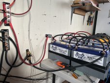
Jon, do you own a wire manufacturer? You're using wire like it's FREE! LOL ")
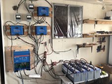
I'm concerned about the 300 amp fuse on the wall in the first picture. Looks like either ANL or MEGA. With that much LiFePO4 in that bank it should be a Class T fuse.
I'm concerned about the 300 amp fuse on the wall in the first picture. Looks like either ANL or MEGA. With that much LiFePO4 in that bank it should be a Class T fuse.
I'm confused. In the first picture above there are 6 batteries. It looks like they are connected in series. But maybe I'm not following the cable right?
Yes, I realize I need a class T fuse, they’re not easy to find. Good catch ?Jon, do you own a wire manufacturer? You're using wire like it's FREE! LOL
I'm concerned about the 300 amp fuse on the wall in the first picture. Looks like either ANL or MEGA. With that much LiFePO4 in that bank it should be a Class T fuse.
Yes, I realize I need a class T fuse, they’re not easy to find. Good catch ?
OK. Don't put too much stress on the system.
I have a Battle Born Batteries tied in series parallel.I'm confused. In the first picture above there are 6 batteries. It looks like they are connected in series. But maybe I'm not following the cable right?
Attachments
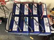
Nevermind. Figured it out. 48v.
I got the diagram off the Internet as a 48 V system. All wires go to the busbars. I do not think it was the best choice though. But hey, it was my first build. ?Aren't all eight of those in series? Which makes 96 volts?
Attachments
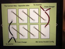
You have the connections right. However, the inverter and charger both need to go through the shunt, not connected directly to the battery.
All connections route through BusbarsYou have the connections right. However, the inverter and charger both need to go through the shunt, not connected directly to the battery.
All connections route through Busbars
OK. In the pictures, they do. In the drawing, they don't.
I’m not sure if it would make a difference, but I don’t pretend to be an expert on electricity! ?OK. In the pictures, they do. In the drawing, they don't.
Attachments
Similar threads
- Replies
- 16
- Views
- 347
- Replies
- 2
- Views
- 171
- Replies
- 7
- Views
- 247
- Replies
- 4
- Views
- 197