Paulfrench35
New Member
@Sleeper85
Thank you for this detailed explanation. I now better understand the usefulness of ESP32.
Thank you for this detailed explanation. I now better understand the usefulness of ESP32.


I noticed my deye displays the lower of the temperature T1 or T2 instead of the highest one.
Edit: ok
Hi, for a very new newbie, could you explain in non technical terms, what your post actually means.After much searching I found the JK BMS, with it's 2A built-in active balancer it was just what I was looking for.
I wanted to connect my JK-BMS to my inverter like a commercial battery to ensure the inverter knows what the battery is up to in terms of Charging, Discharging, Alarms etc.
If you buy the CAN model, it does not support any standard battery protocol that energy storage inverters support.
All that changes now, as I have enabled CAN bus support for standard JK BMS RS485 models.
This will allow your JK BMS to communicate with any inverters that support Goodwe and Pylontech Low voltage batteries via CAN bus (Protocol compatible with Pylontech V1.3 and Goodwe V1.5)
New: Hardware interface kit(plug and play) info here
Thought this may help some others who would like inverter comms with their JK BMS.
My work can be found here: jk-bms-can
Sends over CAN bus to inverter:
Note:- Support for only one BMS CAN connection per inverter, see here more info on creating larger capacity packs
- Battery Voltage
- Battery Current (+charge, -discharge)
- State of Charge (SOC)
- State of health (SOH)
- BMS Temperature
- Charging Voltage
- Charging Amps
- Discharge min Voltage
- Battery name
- Alarms: Cell over/under voltage, Charge/discharge over current, High/low Temp, BMS fault
- Charging logic: Charging logic, now charges with constant current(CC) to the absorption voltage, then has an absorption timer (Constant Voltage, user configurable time), with rebulk feature (user configurable offset from absorption voltage). The charging logic is designed to stop charging once absorption phase has completed (no keeping the battery on float) and reduce micro cycling.
Early stages are under way to support multiple BMS, but need funding to purchase additional hardware, please consider supporting me if you would like to see this functionally, early access code with be made available in the Alpha testers membership once funding goals are reached:
see here for more info: Multi BMS info
NOTE: ESP32 has a bug that causes WDT reboot if no other devices on CAN bus to ACK the packets.
If you try to run without inverter it will not work as it will constantly WDT reboot!
There is an early access beta version available that works around no inverter(CAN bus requires 2 devices to work).
Home Assistant native integration via ESPHome:
View attachment 123038
- Battery control switches to manage battery remotely
- Charging request status
- Absorption voltage (slider)
- Charging current max (slider)
- Charging enabled/disabled
- Discharging enabled/disabled
- Charging manually (top balancing)
- All BMS sensor values
I'm using it in my production environment which consists of:
I have set up Pateron to help fund future development.
- Goodwe GW5000S-BP 5kW inverter
- Goodwe GM3000 3 phase Smart meter cabled back to inverter (you can also use the GM1000 if you have single phase)
- 16 * EVE LF280K batteries in series for nominal 51.2v
- JK-BMS 150A model JK-B2A24S15P
- JK RS485 module (you don't need this if your ESP32 is near the JK-BMS)
- ESP32 model esp32doit-devkit-v1
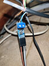
- TJA1050 CAN bus to TTL module 4.7K resistor for 5V to 3.3v level shift.
- RS485 to TTL module (you don't need this if your ESP32 is near the JK-BMS)
- Various safety devices: Fuse and ZJ Beny125A DC circuit breaker etc.
Additional info will be published to "Be in the know" Pateron membership levels and above like:
What development is coming soon
Development that has been completed and is in Alpha/Beta testing
Get early access to Alpha/Beta code for testing (in those tiers)
Polls to determine future features etc.
Help fund goals to purchase additional hardware like multiple BMS support
Hi, for a very new newbie, could you explain in non technical terms, what your post actually means.
I thought that the BMS did not need to communicate with the inverter, as it's purpose is to monitor and control the battery charging only.
I am currently researching building my own set of batteries and trying to decide what sort of 200a BMS to buy. I came across this thread by accident and it has greatly confused me.
Appreciate any clarifications you could give me. Thank you.
I think I see where my confusion lies. When you say "inverter/charger" your talking about a AIO inverter with inbuilt MPPT. Rather than a stand alone mppt and a stand alone inverter. Like in my case the MPPT is a Victron solar smart, connected to the batteries via smart shunt to a Lynxx Distributor which then connects to my Victron Multiplus inverter. So the smart shunt carries the communications between batteries and MPPT to control charging etc. Is that what I am mixing up perhaps.?The advantage of communication with the inverter/charge controller is that you can have the BMS control the parameters on the fly based on conditions such as temperature, state of charge, etc. You can for example slow down charging if the (ambient) temperature is getting too high, or slow down charging when the state of charge is high to give the balancer time.
Do you need it? Not really. I run my system without any communication at all. If you set your parameters, and they work for you, you don't need it and it just adds a layer of complexity. I consider the (JK in my case) BMS only as the last line of defense to protect my cells, nothing else.
I think I see where my confusion lies. When you say "inverter/charger" your talking about a AIO inverter with inbuilt MPPT. Rather than a stand alone mppt and a stand alone inverter. Like in my case the MPPT is a Victron solar smart, connected to the batteries via smart shunt to a Lynxx Distributor which then connects to my Victron Multiplus inverter. So the smart shunt carries the communications between batteries and MPPT to control charging etc. Is that what I am mixing up perhaps.?
When you say "inverter/charger" your talking about a AIO inverter with inbuilt MPPT. Rather than a stand alone mppt and a stand alone inverter. Like in my case the MPPT is a Victron solar smart, connected to the batteries via smart shunt to a Lynxx Distributor which then connects to my Victron Multiplus inverter. So the smart shunt carries the communications between batteries and MPPT to control charging etc. Is that what I am mixing up perhaps.?
# V1.15.3 Sleeper85 : Add 'CAN Protocol Settings' and new CAN ID based on the SMA and Victron protocol (alpha)
# V1.15.2 Sleeper85 : Improved Alarm handling, all alarms will set charge/discharge current to 0A and set 'Charging Status' to Alarm

@Sleeper85 i have Growatt inverter SPF5000ES and JK-B2A20S20P, your .yaml run with ?


The blue LED flashes, what does that mean?
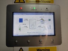
Inverter shows message 04 "Low battery level" since I connected ESP32. What value in your program is used for comparison?


Another important thing about connecting with Home Assistant.
If your ESP32 is not connected with Home Assistant it will reboot every 15 minutes. This is the normal behavior of ESPHome if HA is not connected to the ESP32 API. This is not a bug to be resolved but a mechanism put in place by the ESPHome team to correct a possible problem with the connection to the API.
So I prefer to explain to you how to disable the API if you don't use Home Assistant.
Just comment out the "api:" line in the configuration file before flashing the ESP32.
View attachment 186286
The same goes for the WiFi connection, if the ESP32 is not connected it will reboot every 15 minutes. If you do not want to connect the ESP32 to the WiFi network you can comment on all the lines below.
View attachment 186285
Or you can use reboot_timeout to increase it from the 15min.
@Sleeper85 I will try your new version and I will give you a return.
How can I stop scrolling any data column right to see alarm messages, etc... ??
Confirmed working on Solis!
Specifically the RHI-3.6K-48ES-5G. I had to switch to a different CAN transceiver (TI SN65HVD230). Something about the Solis and many other newer inverters only accepting the 3.3V CAN and not the 5V CAN of the TJA1050. I think Uksa007 also mentioned that he had switched to a TI part.
The SN65HVD230 is a native 3.3V part so it doesn't require the 4.7K resistor on the RX. Also it is powered by 3.3V so don't connect it to 5V!
Thank you Sleeper85 for continuing this project. Had been using it without issue with my Growatt SPF5000ES for the last year and plan to continue doing so with the Solis!
To be honest I just took a fresh clone of the repo this time. Everything is default at the moment.Interesting, I take note of all that.
What CAN IDs do you use with the Solis?
The PYLON 1.2 standard alone or with other extra IDs?
To be honest I just took a fresh clone of the repo this time. Everything is default at the moment.