You are using an out of date browser. It may not display this or other websites correctly.
You should upgrade or use an alternative browser.
You should upgrade or use an alternative browser.
JK BMS CAN bus comms now possible for inverters that support Goodwe and Pylontech batteries
- Thread starter uksa007
- Start date
So the standard one without heat+can?@ChrisG B2A20S2P works perfecly.
Paulfrench35
New Member
Yes !
Thanks, just pull the trigger on 6 of them.Yes !
Sleeper85
Sunday handyman
- Joined
- Nov 28, 2022
- Messages
- 503
Thanks, just pull the trigger on 6 of them.
Attention! the standard BMS is OK but this project only works with one BMS connected to the inverter.
This is not code with multi-bms interfaces like uksa007 sells.
Thanks and understood. So I couldn't hook multiple to a VenusOS Pi? Understood not daisy chained but one per USB?Attention! the standard BMS is OK but this project only works with one BMS connected to the inverter.
This is not code with multi-bms interfaces like uksa007 sells.
Sleeper85
Sunday handyman
- Joined
- Nov 28, 2022
- Messages
- 503
Thanks and understood. So I couldn't hook multiple to a VenusOS Pi? Understood not daisy chained but one per USB?
I'm not a Victron expert, if you have several CAN bus inputs on the Pi Venus OS like the board shown by Andy a little while ago. Maybe it's possible to connect several BMS seen as independent batteries. To test, I can't confirm that it will be OK.
Why not buy the new JK BMS in order to communicate the batteries together and have a single CAN link to Victron?
Sleeper85
Sunday handyman
- Joined
- Nov 28, 2022
- Messages
- 503
Something about the Solis and many other newer inverters only accepting the 3.3V CAN and not the 5V CAN of the TJA1050.
The SN65HVD230 is a native 3.3V part so it doesn't require the 4.7K resistor on the RX. Also it is powered by 3.3V so don't connect it to 5V!
Thanks for the info, I added it in the README.
And I modified the schematics like this:
Code:
3.3V CAN BUS

              RS485-TTL               RS232-TTL                CAN BUS (3V3)
┌──────────┐            ┌──────────┐             ┌────────────┐              ┌──────────┐
│          │<TX------RX>│16      23│<TX-------TX>|            |              |          |
│  JK-BMS  │<RX------TX>│17      22│<RX-------RX>| SN65HVD230 |<---CAN H --->| Inverter |
│          │<----GND--->│   ESP32  │<----GND---->|    CAN     |<---CAN L --->|          |
│          │     5V---->│VIN    3V3│<---3.3V---->|            |              |          |
└──────────┘            └──────────┘             └────────────┘              └──────────┘


5V CAN BUS

              RS485-TTL               RS232-TTL                CAN BUS (5V)
┌──────────┐            ┌──────────┐             ┌────────────┐              ┌──────────┐
│          │<TX------RX>│16      23│<TX-------TX>|            |              |          |
│  JK-BMS  │<RX------TX>│17      22│<RX--4K7--RX>|  TJA1050   |<---CAN H --->| Inverter |
│          │<----GND--->│   ESP32  │<----GND---->|    CAN     |<---CAN L --->|          |
│          │     5V---->│VIN    VIN│<----5V----->|            |              |          |
└──────────┘ └──────────┘ └────────────┘ └──────────┘I needed a new BMS for new packs, wanted active balancing integrated so chose the previous version. Looks like the new one still has several issues, even with the latest firmware. Also got them for $100/each, not sure if that is a great price but seemed to be. Integration is not a MUST, more of a nice to have. Voltage and SOC via shunt has worked fine for a long time.I'm not a Victron expert, if you have several CAN bus inputs on the Pi Venus OS like the board shown by Andy a little while ago. Maybe it's possible to connect several BMS seen as independent batteries. To test, I can't confirm that it will be OK.
Why not buy the new JK BMS in order to communicate the batteries together and have a single CAN link to Victron?
uksa007
Solar Enthusiast
- Joined
- May 26, 2022
- Messages
- 239
Meh open source = open wounds.
Been there done that seen too many fights and drama.
Closed sourced, fairly price, with proper support wins in my opinion.
All those wanting open source have no idea on what do with it they just like the way it sounds. All they do is bug the original developer and ask, plead, and then demand changes all for free.
No thanks.
Yep you are totally right.
Too many people that caused me to stop supporting this open source, as they:
- Complain about everything
- Want everything for free
- Don't provide any financial support
- Want many hours of support for free, to help build hardware/firmware which they have no experience with.
- Generally have no clue
- Spent 1000's of hours researching how inverter communications work.
- Spent 1000's of hours writing code and testing.
- Spent 1000's of hours designing PCB, sourcing parts
- Manufactures the Boards.
- Provides support
And if they bothered to check his licence allows for all kinds of use.

Last edited:
uksa007
Solar Enthusiast
- Joined
- May 26, 2022
- Messages
- 239
This project is based on that of syssi who also certainly spent a lot of time programming the part concerning the communication with JK-BMS but I think that syssi will not receive any $ earned by uksa007.
A project based on another open-source project must cite its sources.
uksa007 added the CAN part but without the components developed by syssi (and perhaps other people) these applications would be nothing.
So he takes the work that other people have offered to the community and then sells it.
What bothers me the most in this story is that at the beginning he starts the project in the philosophy of an open-source project with a diagram with the components to assemble etc. and then afterwards, without saying anything, he completely changes direction.
So regarding prices, a simple small board with an ESP32 and 5 components sells for more than a BMS!
I'm not the only one who finds this crazy.
uksa007 is not clear at all and doesn't get it right.
I use Solar Assistant which is a great application, I paid for a lifetime license for $50 and I receive upgrades with new features every month (beta tester program).
Do you really think that I will pay $50/month to become a beta tester of the uksa007 application?
Finally, I'm not against paying to support the work carried out but not under the current conditions.
The cost to build and manufacture a product is not the cost of the raw materials.
There is significant cost in labour to build the product, manage the inventory (import taxes), packing and shipping, payment processing fees, and provide support
Not to mention the 1000's of hours research and development that went into the code, and its continual improvement.
There is no ongoing subscription required.
If you bothered to check syssi licence is permissive:

Yep you are totally right.
Too many people that caused me to stop supporting this open source, as they:
If they weren't so busy complaining about everything they would see that it is me who:
- Complain about everything
- Want everything for free
- Don't provide any financial support
- Want many hours of support for free, to help build hardware/firmware which they have no experience with.
- Generally have no clue
If they spent five minutes they would see that Syssi code is simple serial reading
- Spent 1000's of hours researching how inverter communications work.
- Spent 1000's of hours writing code and testing.
- Spent 1000's of hours designing PCB, sourcing parts
- Manufactures the Boards.
- Provides support
And if they bothered to check his licence allows for all kinds of use.
View attachment 186942
I don't think anybody here was downplaying your contribution, or claiming your efforts were trivial. Though, I hate to be the one to point out that it seems this is exactly what your are claiming in regards to syssi's "simple serial reading" work, yet still valuable enough to start your repo on a fork of theirs. Even syssi's work would be meaningless without the work of esphome, homeassistant, and all related open source contributions. I am a software developer myself, so yes, I have spent the 5 minutes (and more) to fully understand what is happening from a code perspective.
I'm not sure why the license was brought up as well... did someone claim that you were not allowed to continue down your path for licensing reasons? However you choose to continue your project, is completely up to you. Since you brought it up... per the Apache 2.0 license, all copies of the source, or derivative works, must be provided a copy of the license. I see you have removed the LICENSE file from the repo with the purge, so you might want to check on that to remain compliant... Yes, it is permissive, but read the rest of the first sentence.
Back to the point of open source - as you can see from the continuation of the thread, people in general tend to build and share collaboratively. You can choose to leverage these open contributions in the form of a commercial product for sale, as many companies do, that is your choice. Or you can continue down a closed path, that is your choice as well. Nobody is forcing you one way or the other.
Once again, thank you for your contributions. I'm sure those who prefer a more polished, commercial solution, will continue to support you. On the same note, the more hands-on members of the community will continue down a parallel path to also provide an open solution. Neither one is more correct than the other, everyone has their preference.
Last edited:
uksa007
Solar Enthusiast
- Joined
- May 26, 2022
- Messages
- 239
I don't think anybody here was downplaying your contribution, or claiming your efforts were trivial. Though, I hate to be the one to point out that it seems this is exactly what your are claiming in regards to syssi's "simple serial reading" work, yet still valuable enough to start your repo on a fork of theirs. Even syssi's work would be meaningless without the work of esphome, homeassistant, and all related open source contributions. I am a software developer myself, so yes, I have spent the 5 minutes (and more) to fully understand what is happening from a code perspective.
I'm not sure why the license was brought up as well... did someone claim that you were not allowed to continue down your path for licensing reasons? However you choose to continue your project, is completely up to you. Since you brought it up... per the Apache 2.0 license, all copies of the source, or derivative works, must be provided a copy of the license. I see you have removed the LICENSE file from the repo with the purge, so you might want to check on that to remain compliant... Yes, it is permissive, but read the rest of the first sentence.
Back to the point of open source - as you can see from the continuation of the thread, people in general tend to build and share collaboratively. You can choose to leverage these open contributions in the form of a commercial product for sale, as many companies do, that is your choice. Or you can continue down a closed path, that is your choice as well. Nobody is forcing you one way or the other.
Once again, thank you for your contributions. I'm sure those who prefer a more polished, commercial solution, will continue to support you. On the same note, the more hands-on members of the community will continue down a parallel path to also provide an open solution. Neither one is more correct than the other, everyone has their preference.
Every single product/software is based on work by someone else, if the eg IEEE didn't make the standards no one would have standards for anything, nothing would work.
Syssi code saved me a couple of hours work, not having to write my own serail reading code, had I know it was going to going be perceived that I just stole someone's work and put lipstick on it, I would have just written it myself, but then everyone would complain that I used ESPhome, or IEEE standards. You can't make everyone happy.
If you don't support the open source version high likelihood of many unhappy people as they can't get it to work, which has a negative impact on your name and hardware product.
Better in my opinion to offer just one solution, which I believe solves all the problems for everyone:
Hence the Hardware Interface kit was born.
Removed frustration for the user trying to build hardware/firmware, as many have little to no electronics and coding experience.
The user ends up with a professional board, as opposed to hacked together modules which are unreliable at best.
I don't spend all my time trying to support people building hardware and compiling firmware, breaking the code, etc.
It is build and tested, plug and play.
Win Win.
Yes it cost money, life is not alway free.
Last edited:
uksa007
Solar Enthusiast
- Joined
- May 26, 2022
- Messages
- 239
The Heat+CAN mode has Heat output and CAN(not used as it is proprietary JK protocol)So, if we can get back to the real topic of integrations. What is the benefit of the normal JK B2A20S2P vs B2A20S2P Heat+CAN in the context of either branch of code here. Doesn’t seem like there is but want to confirm.
Both will work, if you need the heat function get the Heat version if not, get the non Heat version.
Thanks @uksa007.The Heat+CAN mode has Heat output and CAN(not used as it is proprietary JK protocol)
Both will work, if you need the heat function get the Heat version if not, get the non Heat version.
Sleeper85
Sunday handyman
- Joined
- Nov 28, 2022
- Messages
- 503
V1.15.5 on GitHub
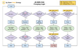
I decided to deactivate the API reboot every 15 minutes if there is no connection with HA, I think we should prevent the ESP32 from rebooting which could happen during a Bulk charge. I also adapted the default discharge current to 120A therefore 6000W.
In addition, as I received a lot of questions regarding the operation of the charging logic I created the diagram below to make it clear.

Last edited:
arzaman
New Member
- Joined
- Nov 9, 2022
- Messages
- 42
I'd like to share a neat and simple hardware alternative for implementing the protocol converter.
I utilized components from M5stack
ATOM Lite, an ESP32 pico controller
ATOMIC CANBus Base (based on CA-IS3050G transceiver)

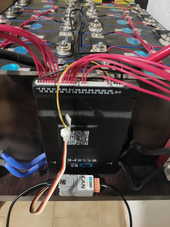
By simply connecting the 'grove' port to the JK-BMS TTL GPS port with a straightforward JST cable adapter and routing the CAN output to the Deye sun-5k-sg03lp1-eu inverter, everything functions seamlessly, as demonstrated.
The power supply is currently temporary from the USB-C Atom port.

My next steps involve integrating a DC-DC step-down converter to power the circuit (and possibly my Rpi running home assistant) from Vbat. Additionally, I plan on incorporating an OLED display to visualize real-time relevant parameters like State of Charge (SoC) and voltage.
enjoy
Davide
I utilized components from M5stack
ATOM Lite, an ESP32 pico controller
ATOMIC CANBus Base (based on CA-IS3050G transceiver)

By simply connecting the 'grove' port to the JK-BMS TTL GPS port with a straightforward JST cable adapter and routing the CAN output to the Deye sun-5k-sg03lp1-eu inverter, everything functions seamlessly, as demonstrated.
The power supply is currently temporary from the USB-C Atom port.

My next steps involve integrating a DC-DC step-down converter to power the circuit (and possibly my Rpi running home assistant) from Vbat. Additionally, I plan on incorporating an OLED display to visualize real-time relevant parameters like State of Charge (SoC) and voltage.
enjoy
Davide
What software is running on the controller? Do you have a complete build sheet/instructions?I'd like to share a neat and simple hardware alternative for implementing the protocol converter.
I utilized components from M5stack
ATOM Lite, an ESP32 pico controller
ATOMIC CANBus Base (based on CA-IS3050G transceiver)
View attachment 187756
By simply connecting the 'grove' port to the JK-BMS TTL GPS port with a straightforward JST cable adapter and routing the CAN output to the Deye sun-5k-sg03lp1-eu inverter, everything functions seamlessly, as demonstrated.
The power supply is currently temporary from the USB-C Atom port.
View attachment 187757
My next steps involve integrating a DC-DC step-down converter to power the circuit (and possibly my Rpi running home assistant) from Vbat. Additionally, I plan on incorporating an OLED display to visualize real-time relevant parameters like State of Charge (SoC) and voltage.
enjoy
Davide
arzaman
New Member
- Joined
- Nov 9, 2022
- Messages
- 42
What software is running on the controller? Do you have a complete build sheet/instructions?
the one kindly supported and maintained open source by @Sleeper85 in his repo (great thanks)
GitHub - Sleeper85/esphome-jk-bms-can
Contribute to Sleeper85/esphome-jk-bms-can development by creating an account on GitHub.
Sleeper85
Sunday handyman
- Joined
- Nov 28, 2022
- Messages
- 503
What software is running on the controller? Do you have a complete build sheet/instructions?
He adapted the YAML available on GitHub for the ESP32 pico.
CAN board base (Atom CAN)
ESP32 pico board (Atom Lite)
Just buy these two components and put them together like Lego.
I could add a YAML dedicated to this solution for those who are interested.
You can purchase both components as a kit.
M5Stack Official Store (Aliexpress)
Last edited:
arzaman
New Member
- Joined
- Nov 9, 2022
- Messages
- 42
He adapted the YAML available on GitHub for the ESP32 pico.
CAN board base (Atom CAN)
ESP32 pico board (Atom Lite)
Just buy these two components and put them together like Lego.
I could add a YAML dedicated to this solution for those who are interested.
You can purchase both components as a kit.
Exactly !
I just edit few parameters in the original yaml file
here are the modifications
Code:
# GPIO pins your CAN bus transceiver ATOMIC CANBus Base (CA-IS3050G)
  can_tx_pin: GPIO22
  can_rx_pin: GPIO19
# GPIO pins your JK-BMS RS485(TTL) is connected to the grove port of ATOM lite
  tx_pin: GPIO32
  rx_pin: GPIO26

  esp32:
  board: m5stack-atom
  framework:
    type: arduino
on top of this due to my config
I enable Home Assistant API
I fixed IP address on ESP32
Cable connection between RS232 TTL JK port and M5stack Atom port is very simple just GND, TX, RX
Thanks. And this replaces that 'other' expensive board for the JK and then can interface with many inverters? Assume there is no ability to chain these together for multiple packs?He adapted the YAML available on GitHub for the ESP32 pico.
CAN board base (Atom CAN)
ESP32 pico board (Atom Lite)
Just buy these two components and put them together like Lego.
I could add a YAML dedicated to this solution for those who are interested.
You can purchase both components as a kit.
M5Stack Official Store (Aliexpress)
Last edited:
arzaman
New Member
- Joined
- Nov 9, 2022
- Messages
- 42
Thanks. And this replaces that 'other' expensive board for the JK and then can interface with many inverters?
If you have only one battery bank and inverter, I would definitely say yes!
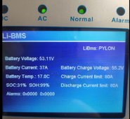
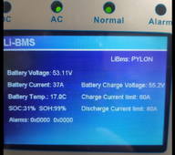
here screenshot of my Deye inverter configured as "Pylon"

I followed the instructions to compile it on EspHome, connected the two cables, and it's working perfectly (along with Home Assistant monitoring).
The only 'limitation' is that to power the M5stack Atom, you currently need to connect a USB-C cable to a 5V power supply. I'm in the process of developing a simple DC-DC converter PCB to directly draw 5V from the Vbat of the JK-BMS port. This way, it will become a plug-and-play autonomous solution
Similar threads
- Replies
- 1K
- Views
- 40K
- Replies
- 47
- Views
- 9K
- Replies
- 27
- Views
- 695
- Replies
- 2
- Views
- 437
- Replies
- 9
- Views
- 650


