diy solar

diy solar

Renogy DC DC Charger w/ MPPT

Thanks Randy. I *think* I did just that but can't be sure. I will do it in that order when I get home.
......................
......................
EDIT: I just noticed you said to use the correct password for the bluetooth connection. It has never asked for one, only for an admin password to change settings.
I'm getting to the point that I do not remember all the details in order. I think my iPhone ask me if I give permission to BT-2 device for bluetooth pairing (only on the first try). Of course, I answered YES. Then it ask for a password, I guess that's the admin password. I had changed that password some time along the way. Changed back to default, changed it again. Al I'm saying is be sure and use the password that is current for the device.

Best of luck, once I got the BT-2 connected to the phone, everything else seemed to work as best can be expected considering Renogy gave me next to no information in their manual for the device.

Settings, I posted my settings in the BT-2 thread noted above. I made changes and posted the changes. i made further comment in the reply to harley above. My first comment for you would be, do you really want the max voltage seen by the LiFePO4 battery to be greater than 14.6 V ?
 
I have done all that multiple times. I have checked and my phone will pair with other devices and I rebooted it a couple of times. I left it all shut off while I went to work for a 48 hour shift. I will give it all another shot when I get home and read through the linked thread. Thanks much for taking the time to help though!
OK boondocks, if you choose to, we could use a messenger or messaging chat/video to talk and work thru this, or Zoom for that matter. Just let me know. Once you get it synced, you can move on. Android or iPhone ?
 
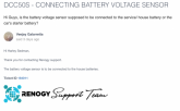
I figured the manual quote would be sufficient to instruct the correct BVS wiring. But I could always be wrong.
I see your point now smoothJoey. There is really no specific battery specified either in text of image. Could be either battery, start or storage. I just got carried away because of my experience with other dc-dc charging devices. These devices need to know the exact start battery (input battery) voltage state to make charging decisions. The conductors from the start battery to the DCC50S are usually long enough to have some voltage drop from end to end because of the higher current in these conductors compared to the storage battery current (usually shorter wires than starter battery cables).
So once again the Renogy manual is not written concisely enough for everyone to get it right.
 
These devices need to know the exact start battery (input battery) voltage state to make charging decisions.

Not really.
The charger needs to know the target battery voltage from the battery's perspective.
It needs to know if the alternator is running though.
 
Last edited:
OK boondocks, if you choose to, we could use a messenger or messaging chat/video to talk and work thru this, or Zoom for that matter. Just let me know. Once you get it synced, you can move on. Android or iPhone ?

Very generous offer Randy! When I get home tomorrow I will turn it all back on in the sequence you laid out. If that doesn't work I will shoot you a PM. Thanks!

Oh, and Android.
 
Very generous offer Randy! When I get home tomorrow I will turn it all back on in the sequence you laid out. If that doesn't work I will shoot you a PM. Thanks!

Oh, and Android.
Have another Zoom meeting at 7:15 PM tomorrow night. Other than that, I'll give it a try.
 
Not really.
The charger needs to know the target battery voltage from the battery's perspective.
It needs to know if the alternator is running though.
Agree, the dc-dc charger needs to know the output batteries Absorb and Float voltages, these are in the BT-2 settings.
The dc-dc charger needs to monitor the input batteries voltage to insure the input battery has been recharged by the alternator after engine start up (usually looks for 13.2 v or greater) and it needs to know while charging the output battery if the input battery voltage drops below 9.0 v so the alternator power can be used to charge the input battery back up before continuing to charge the output battery.
 
Last edited:
Took a look at your charge settings, thanks Randy. Assuming that I can get it to work again, my one last setting question is the boost voltage. Fortune says 3.65 per cell, or 14.6 for a 12V pack. Is this a little high? If I do want to use 14.6, obviously I need to raise the high voltage disconnect and charge limit voltage.
 
Took a look at your charge settings, thanks Randy. Assuming that I can get it to work again, my one last setting question is the boost voltage. Fortune says 3.65 per cell, or 14.6 for a 12V pack. Is this a little high? If I do want to use 14.6, obviously I need to raise the high voltage disconnect and charge limit voltage.
-I would use High Voltage Disconnect 14.6 v (this assuming the device looks at the storage battery, and not the start battery for this voltage, there is no info with the device or app that defines this voltage point source). I never want my 12v LiFePO4 battery to see more than 14.6 v.
-I would use Charge Limit Voltage 14.4 v because that is what BB stated the charge limit voltage should be.
-I would use Equalizing Charge Volt 14.4 v because I never want to apply an equalize voltage, but if it happens, I want to, limit that voltage to charge limit voltage.
-I would use Boost Charge Volt 14.4 v because this is the voltage i want the boost charge phase to end at, and the voltage I want the Absorb Charge phase to be held at.
-I would use Float Charge 13.8 v because my LiFePO4 battery is at 100% SOC with a resting voltage of 13.6 v , I want to use the solar power as much as possible to provide any incidental fluctuating dc power needs during the day (like water pump, led lights, water heater control...) and still maintain battery at 100% SOC for when the sun goes down. I also noticed that at a float of 13.8 v my battery does no accept any more current.
-I would use Boost Char Return 13.6 v because my LiFePO4 battery is at 100% SOC with a resting voltage of 13.6 v , I want to use the solar power as much as possible to provide any dc power needs during the day (like water pump, led lights, water heater control, inverter if I use AC during the day...) and still maintain batter at 100% SOC for when the sun goes down. By setting a high Boost Return voltage, the solar will be used to its max to power dc loads during the day and keep the battery as fully charged as the solar cell capacity can handle.

That's my settings and logic for them at this time, these settings may change over time with experience and education.

Your settings are yours, but just remember the high cost of that LiFePO4 battery when it comes to high voltage limit, low voltage limit & max charge/discharge rate that can severely reduce or end the life of your battery.
 
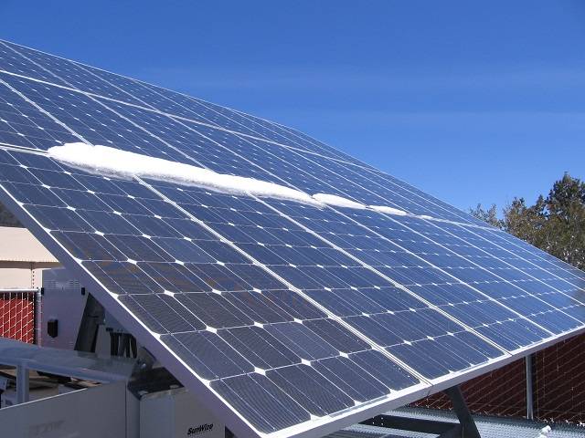
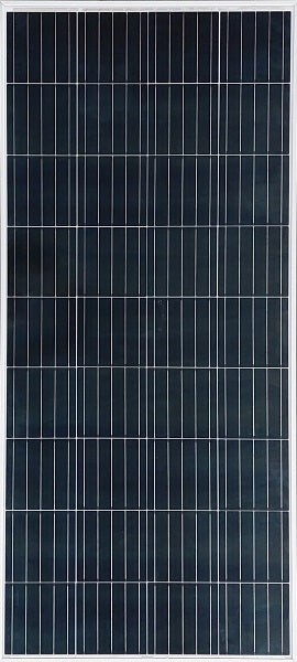
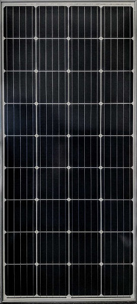
I know the solar plan is for 4 100 watt panels but could 2 200 watt panels work?
I think so, as long as the open circuit panel voltage Voc is <= the DCC50S rating (25 v dc), and you connect them in Parallel.
I think the MCC50S is rated for 660W input from solar. I plan to use three 210AH '12v' solar panels. I do not believe that my panels will ever produce Vmpp, Impp setting flat on the top of my camper.
 
Last edited:
Randy, you da man! I used your secret handshake and I connected right up. I used your settings from the other thread. I will have to go for a spin soon and see it actually do it, but so far so good.

Man, I needed a win today. The wind took down my main radio antenna the other day and I have been out there for hours trying to use a giant sling shot to get it back up 50' + over a tree limb where it needs to be.

I think so, as long as the open circuit panel voltage Voc is <= the DCC50S rating (25 v dc), and you connect them in Parallel.
I think the MCC50S is rated for 660W input from solar. I plan to use three 210AH '12v' solar panels. I do not believe that my panels will ever produce Vmpp, Impp setting flat on the top of my camper.

I agree, no way you get VOC out of a panel sitting flat on a van. I had an email exchange with Renogy as this issue came up in another thread. Here is what they had to say:

"Our panels output max 22.5 under normal conditions. Voltage can go higher if there is colder weather. The controller will not allow that voltage to go through and over time, say if it was cold in the morning, the panels should heat up and lower that voltage to start working again. But I'm not sure what the max time limit you want over 25v . It's a super rare case that would happen.

VOC should stay open for a long time, but since this thing is advanced and switches and isolates we can't fully attest how long you can keep it in a fault position. However, because it's listed as a protection, we imagine it can stay like that at most probably a day or 2 and if it experiences more issues the DCDC will probably fault and enter protection mode anyway

Since they are our panels the VOC is 22.5v It'll be fine. It's the temperature bringing that VOC up. You can either add a panel disconnect or just monitor it, though I don't think it'll be a problem."

While it is hard to make complete sense of that there is some sort of over voltage protection built in. My panels (not Renogy) could in theory float a volt or so high under ideal conditions. I'm not going to lose any sleep over it.
 
All good news. Now make note (notes) of how you rebooted and got the bluetooth connected......for next time. If the DCC50S goes into high voltage cut out, you have to do the reboot to reset it.
 
I think so, as long as the open circuit panel voltage Voc is <= the DCC50S rating (25 v dc), and you connect them in Parallel.
I think the MCC50S is rated for 660W input from solar. I plan to use three 210AH '12v' solar panels. I do not believe that my panels will ever produce Vmpp, Impp setting flat on the top of my camper.
I have Will's diagram for the 4 100 watt panels in parallel but I was hoping to take up less space on my RV's roof and use 2 200 watt panels. Which is the safer bet? Just out of curiosity... what brand of panels are you going to get?
 
NO, I mean you need to use a BT-2 to change the battery charge settings if you want to leave the DCC50S hooked up to the solar panel and battery continuously.

The reason is that the DCC50S default 'Li' setting is 14.4 v for Absorb & Float. I discovered this by testing the battery under solar charge with the DCC50S.

Once the battery is charging in the Boost mode to the 14.40 v Absorb voltage point and the charge current approaches 0 A , the battery charge voltage should be reduced to a lower Float charge voltage if you want the battery to have a longer life. If the battery is continuously held at 14.40 v after 100% SOC, its life will be reduced.

I plan to use 13.8 v as the Float voltage (PWM charging). This will supply RV parasite electrical loads (smoke, propane detectors, DC refer control, furnace/ac/water heater control) and hold battery at 100% SOC. If there is additional DC load drawn from the battery while it is in the Float Mode, the Float charge voltage will slowly dwindle as more power is drawn from the battery than the DCC50S/Solar can supply at 13.8 v float. At the battery 13.6 v point (boost charge return point) the DCC50S will return to Boost (MPPT) until the Absorb 14.40v is attained. Then the cycle repeats until the sun goes down.

If you use the DCC50S 'factory default settings' for 'Li' battery (blue light) the battery never goes into a reduced Float charge voltage when it's SOC is 100%. It stays at 14.40 v charge voltage.

No, don't get a BT-2 because it is cool, get it because it is the only tool that will let you change the Battery type to "User" (white light) and then specify settings what will extend the life of your LiFePO4 battery.
Sounds reasonable to me. Thanks, I'll be placing my order for a Renogy BT-2 by the end of the week.

While I've got you here, i'm hoping pick your brain for a little further info if you have time. I've attached an updated wiring diagram of my vehicle mounted system (you will note that I've not yet included the BT-2 in the diagram). With regard to the three shunt/monitors, my intention is to have a:

Renogy 500A monitor (RBM500) as the 'summary' house/ service battery monitor - my goal with this monitor is to display the total charge/energy going into or out of the house/service battery at all times.

Bayite monitor as a 'total DC load' monitor - my goal with this monitor is to display the total DC load/ energy usage of all accessories that are connected to the fusebox at all times.

Bayite monitor as a 'solar power' monitor - my goal with this monitor is to display the amount of energy my solar panel is capturing at all times

Looking at the wiring diagram you can see the Neg from the starter battery, the Neg from the Solar panel, the Neg from the House Batter and the Neg bus bar (found in the middle of the diagram) are all connected to the Neg of the DCC50S.

My question is related to the negative bus bar shown roughly in the middle of the diagram. Will everything work as intended if I connect the Neg from the starter battery and the Neg from the Solar panel to the Neg bus bar (found in the middle of the diagram) instead of the DCC50S?

1593675013637.png
 
The manual that came with my DCC50S was only in English, bad printing. I checked out Renogy webb site and found a much nicer manual, with more info. The BVS info was not in the manual I got with my unit, but it is in the one from their webb site.
Hers's the info:
View attachment 16522


View attachment 16523

Nuff said.
I see your point now smoothJoey. There is really no specific battery specified either in text of image. Could be either battery, start or storage. I just got carried away because of my experience with other dc-dc charging devices. These devices need to know the exact start battery (input battery) voltage state to make charging decisions. The conductors from the start battery to the DCC50S are usually long enough to have some voltage drop from end to end because of the higher current in these conductors compared to the storage battery current (usually shorter wires than starter battery cables).
So once again the Renogy manual is not written concisely enough for everyone to get it right.
here's what Renogy told me on the topic...
 

Attachments

  • 1593675226934.png
    1593675226934.png
    164.4 KB · Views: 33
I have Will's diagram for the 4 100 watt panels in parallel but I was hoping to take up less space on my RV's roof and use 2 200 watt panels. Which is the safer bet? Just out of curiosity... what brand of panels are you going to get?

Lone, in case you don't know the VOC of a solar panel can float high under cold conditions. So when selecting your panels you want to make sure that under cold conditions that you won't exceed the rated max voltage on the DCC50S solar input. As long as the panels you select will meet the specs you can use 100w or 200w panels. Here is an article that explains all this:

.
 
View attachment 1841
Finally reviewed it! People asked me repeatedly, and I was too busy with the solar shed. For the last few days, I tested it like crazy..

And I love it! I should have tested it months ago. Works extremely well, and it's fool proof. I pushed it to every limit, and if it cut off, it would restart a few seconds later.

Dead simple and easy to install for beginners. I really wish I had one of these when I was first adding solar to my RV. Super cheap too, compared to buying a voltage sensitive dc/dc charger and 50 amp mppt. Only downside is solar input voltage is extremely low, so 12v panels need to have branch adapter.

Key features (copied and pasted from renogy):
  • Designed to charge service batteries from two DC inputs—solar panels and alternator.
  • Built-in Maximum Power Point Tracking (MPPT) to maximize the solar power.
  • 3-phase charging profile (Bulk, Boost, and Float) ensures your service battery will be accurately charged at the correct voltage levels to 100%.
  • Built-in Voltage Sensitive Relay (VSR) for easy setup with traditional alternators.
  • Compatible with smart alternators (with variable output voltage).
  • Trickle charges the starting battery via solar panels if the service battery is fully charged.
  • Isolation of the starting battery and the service battery.
  • Temperature and voltage compensation features prolong battery life and improve system performance.
  • Smart Protection Features: battery isolation, over-voltage protection, battery temperature protection, over-current protection, overheat protection, reverse current protection, solar panel and alternator reverse polarity protection.
  • Compatible with multiple battery types: AGM, GEL, Flooded, and Lithium.
  • Compact with a sturdy design, it was built tough for all conditions.

I love it so much, that I created a new solar power package on my website! Dead simple blueprint:

Click here for parts list and schematics
You should also test the Kisae DMT
1250... Less constraints!
 
Very generous offer Randy! When I get home tomorrow I will turn it all back on in the sequence you laid out. If that doesn't work I will shoot you a PM. Thanks!

Oh, and Android.
What Make/Model? In the big Smart BMS thread, there was one guy using a Android phone that was having problems no one else was. He had some off brand Android phone not available in the US and it seemed their particular version of Android OS and their skin overlay was causing the BT App to crash when no one else was having the same problem.
 
I have Will's diagram for the 4 100 watt panels in parallel but I was hoping to take up less space on my RV's roof and use 2 200 watt panels. Which is the safer bet? Just out of curiosity... what brand of panels are you going to get?
Safer is a subjective judgement.
I am using HighTec Solar panels, rated at 210 w, they also have 200 W panels.
You might also check out NewPowa 200 W panel.
For safety, compare the panels ratings with the MCC50S specs. Stay within the MCC50S specs for safety.
 
Sounds reasonable to me. Thanks, I'll be placing my order for a Renogy BT-2 by the end of the week.

While I've got you here, i'm hoping pick your brain for a little further info if you have time. I've attached an updated wiring diagram of my vehicle mounted system (you will note that I've not yet included the BT-2 in the diagram). With regard to the three shunt/monitors, my intention is to have a:

Renogy 500A monitor (RBM500) as the 'summary' house/ service battery monitor - my goal with this monitor is to display the total charge/energy going into or out of the house/service battery at all times.

Bayite monitor as a 'total DC load' monitor - my goal with this monitor is to display the total DC load/ energy usage of all accessories that are connected to the fusebox at all times.

Bayite monitor as a 'solar power' monitor - my goal with this monitor is to display the amount of energy my solar panel is capturing at all times

Looking at the wiring diagram you can see the Neg from the starter battery, the Neg from the Solar panel, the Neg from the House Batter and the Neg bus bar (found in the middle of the diagram) are all connected to the Neg of the DCC50S.

My question is related to the negative bus bar shown roughly in the middle of the diagram. Will everything work as intended if I connect the Neg from the starter battery and the Neg from the Solar panel to the Neg bus bar (found in the middle of the diagram) instead of the DCC50S?

View attachment 16656
Yes, run all the - circuits (as you itemized) to the - bus bar, then one negative from - BB to MCC50S controller. I suggested this before. It would be difficult to get three - circuit termlugs on the MCC50S - term point. I see that you have not added the three switch/CB's I suggested previoussly. You have not yet added a main fuse for the battery either.
 
Last edited:
Yes, run all the - circuits (as you itemized) to the - bus bar, then one negative from - BB to MCC50S controller. I suggested this before. It would be difficult to get three - circuit termlugs on the MCC50S - term point. I see that you have not added the three switch/CB's I suggested previously. You have not yet added a main fuse for the battery either.
Yeah, I posted the same thing for the same reason. Not only just fitting multiple lugs on the MCC50S, but the added stress on that terminal from all the cables. It might be a good idea to step up the size of the ground jumper to the bus bar. If you have two 4AWG ground cables from both batteries and a 10AWG ground wire from the PV panel. It would make sense to me, that the ground jumper be larger than those three cables.
 
Yeah, I posted the same thing for the same reason. Not only just fitting multiple lugs on the MCC50S, but the added stress on that terminal from all the cables. It might be a good idea to step up the size of the ground jumper to the bus bar. If you have two 4AWG ground cables from both batteries and a 10AWG ground wire from the PV panel. It would make sense to me, that the ground jumper be larger than those three cables.
You might want to think about the current flowing in each ground cable, how it relates to where the cables are terminated. I think it is correct to use one 4AWG in the case you note above.
 
Last edited:
Hi everyone, would like to seek some help to share how can i add a solar generator example the Ecoflow Delta or Bluetti AC200 into this system?
taking that i will have the exact setup of have a 12v lithum battery fix in the vehicle but i also wish to have a solar generator charge with the system and once in awhile or when i need to i can bring the solar generator to use out of the vehicle.

thank you everyone in advance.
DC-DC.jpg
 
View attachment 1841
Finally reviewed it! People asked me repeatedly, and I was too busy with the solar shed. For the last few days, I tested it like crazy..

And I love it! I should have tested it months ago. Works extremely well, and it's fool proof. I pushed it to every limit, and if it cut off, it would restart a few seconds later.

Dead simple and easy to install for beginners. I really wish I had one of these when I was first adding solar to my RV. Super cheap too, compared to buying a voltage sensitive dc/dc charger and 50 amp mppt. Only downside is solar input voltage is extremely low, so 12v panels need to have branch adapter.

Key features (copied and pasted from renogy):
  • Designed to charge service batteries from two DC inputs—solar panels and alternator.
  • Built-in Maximum Power Point Tracking (MPPT) to maximize the solar power.
  • 3-phase charging profile (Bulk, Boost, and Float) ensures your service battery will be accurately charged at the correct voltage levels to 100%.
  • Built-in Voltage Sensitive Relay (VSR) for easy setup with traditional alternators.
  • Compatible with smart alternators (with variable output voltage).
  • Trickle charges the starting battery via solar panels if the service battery is fully charged.
  • Isolation of the starting battery and the service battery.
  • Temperature and voltage compensation features prolong battery life and improve system performance.
  • Smart Protection Features: battery isolation, over-voltage protection, battery temperature protection, over-current protection, overheat protection, reverse current protection, solar panel and alternator reverse polarity protection.
  • Compatible with multiple battery types: AGM, GEL, Flooded, and Lithium.
  • Compact with a sturdy design, it was built tough for all conditions.

I love it so much, that I created a new solar power package on my website! Dead simple blueprint:

Click here for parts list and schematics
Will, I plan on adopting your blueprint for the 400 watt plan with the above Renogy DC to DC controller and due to very limited roof space on my Sprinter RV, wanted to use 2 x 200 watt glass panels,....You previously had a recommended set of 200 watt glass panels, but they are no longer listed. Are there no acceptable 200 watt panels available in your opinion? Brian Collins Austin, TX (Village Farm Tiny Home community)
 

diy solar

diy solar
Back
Top