diy solar

diy solar

SI6048-US F605 Failure, TransfNotOpen

Olibri

New Member
Joined
Oct 14, 2020
Messages
19
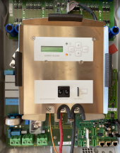
After about a year and a half my slave inverter in a 2 phase configuration has died. What was interesting is that it died in a strange way: AC1 and AC2 were bridged, so since grid power was still up, I didn't notice immediately that the inverter had failed. What was also interesting is that I assumed that without the Master-Slave phase synchronization that the slave would go out of phase, but I didn't notice any issues on my 240V loads and when I measured the voltage across the 2 legs the voltage was stable at about 240V.

1662478795679.png

I pulled the inverter and put it on a bench, then attached separate 48V power to test and was unable to recover the inverter.
In the meantime I had the foresight to buy a backup inverter that was sitting in a box, so I mounted that on the wall and the system is back up with only a couple hours of downtime.
 
F605 is a transfer relay, that shouldn't be a big issue to fix.
 
Sunny Island has the worst problems with Transfer relays sticking.
I have never seen an inverter as sensitive to high current or an unstable grid. If power to ac2 is removed abrubtly while the internal transfer relay is supposed to be closed you might arc and then later stick those relays.

Also I would set your grid and gen nominal current lower (70%) than what the rated 6000 watts per inverter relay is rated for. Remember when you set those settings it is per inverter parallel set . If that is too low of a current to supply loads during internal ac pass through then you need an automatic external bypass contactor or ATS. If you have 2 inverters total in 240v then its whatever the master says . If you had 2 per leg for a total of 4 inverters for 240v you would multiply the value by 2.

If you want to buy relays you can find them online from 3rd party vendors with the Deltron part # but you will need grind off the old relay so each relay pin is isolated on the board and then desolder with a high watt solder gun.

You could also try to take off the clear cover and sand the contacts with a fine sandpaper but this isn't guaranteed to work.

Also if you are in closed loop communication with the inverter via lithium mode and its not approved batteries it could be causing issues. Just a heads up. That can cause brown outs that may cause the transfer relays to close while communication with the batteries is intermittently lost. This is just from my anecdotal experience and what I've seen. Not saying we had it down to a science but it is my best guess as to what was happening.

Finally, if you want to get a board replaced on the US sunny island out of warranty, good luck. They are full replacement only. Sma has decided to treat their old sunny islands like a an ugly red headed step child.
 
Last edited:
You could also try to take off the clear cover and sand the contacts with a fine sandpaper but this isn't guaranteed to work.
Thank you! I popped the cover off the Deltron 375p and pushed on the relay, then powered it up. The error is gone now.
 
Sunny Island has the worst problems with Transfer relays sticking.

I've assumed this was the reason written documentation says to put Sunny Boys in "grid backup" rather than "offgrid" mode.
(So if relay is stuck, and SI can't disconnect SB from grid, at least it can tell SB to remain in UL-1741 mode.)

SMA US now recommends putting SB in offgrid mode instead.
Think they've forgotten something that used to keep German engineers up at night?
 
Last edited:
Once the relay is stuck, the inverter was unusable. It wouldn’t finish boot and just sat at the failure message. I had also tried turning off the grid and that leg went down (the other was still on and powered by the battery + CC).
 
I've assumed this was the reason written documentation says to put Sunny Boys in "grid backup" rather than "offgrid" mode.
(So if relay is stuck, and SI can't disconnect SB from grid, at least it can tell SB to remain in UL-1741 mode.)

SMA US now recommends putting SB in offgrid mode instead.
Think they've forgotten something that used to keep German engineers up at night?
Would you mind expounding on this topic?
 
Grid-interactive inverters are required to meet UL-1741, which ensures that if a wire breaks leaving just the inverter and some wire and loads as an "island", the inverter quickly detects it and shuts off.

Backfeeding a failed section of the grid, especially a transformer, could result in electrocuting a utility lineman. That has happened a number of times with generators. An off-grid inverter incorrectly wired to feed the house without a transfer switch (or interlocked main breaker) would do the same thing. Grid-interactive inverters not performing UL-1741 anti-islanding might continue to feed the grid for an indeterminate length of time. I don't know how great a risk that is (at one point, said to have never been observed in the wild, but was deliberately accomplished with well-matched loads as an engineering experiment.)

In the event Sunny Island relays stuck closed (which somebody said they are known to do), a Sunny Boy in "offgrid" configuration would then be feeding the grid, a potential safety hazard. But if Sunny Boy is in "backup" mode, then Sunny Island would (presumably) NOT send RS-485 signal telling it to switch to off-grid parameters.

I bought Sunny Boy 10000TL-US-12 specifically because it was in SMA's compatibility list (and no current model was at that time.) But I found it failed to ramp down power in response to increasing frequency when configured for "backup". SMA America support told me to put it in Off Grid mode, which did work fine. I later replaced that with 5000US, which does work correctly in "backup".

My suspicion is that SMA America observed the system works correctly (when all its parts work correctly) with Sunny Boy "off grid" installed behind Sunny Island which is on grid. But they may not have known about "FMEA" Failure Modes and Effects Analysis that SMA Germany likely went through to ensure system was safe even if various parts malfunction.
 
If you're interested I can provide you with more details. if you use time delay relays and voltage monitoring relays you can cause it to disconnect before the generator spools too low on gen shutdown and also make it connect only after an inverter has synchronized with a generator that was started but before it's own internal relays close that way you get a fairly flicker free transfer since the sine wave between the generator and the inverter are synchronized and yet you still do the external transfer before the inverter has a chance to close its own internal relays and cause issues that you're trying to avoid by using the external transfer switch in the first place.
Sorry about the run on sentences. I'm using speech to text and in a but of a hurry.
 
Grid-interactive inverters are required to meet UL-1741, which ensures that if a wire breaks leaving just the inverter and some wire and loads as an "island", the inverter quickly detects it and shuts off.

Backfeeding a failed section of the grid, especially a transformer, could result in electrocuting a utility lineman. That has happened a number of times with generators. An off-grid inverter incorrectly wired to feed the house without a transfer switch (or interlocked main breaker) would do the same thing. Grid-interactive inverters not performing UL-1741 anti-islanding might continue to feed the grid for an indeterminate length of time. I don't know how great a risk that is (at one point, said to have never been observed in the wild, but was deliberately accomplished with well-matched loads as an engineering experiment.)

In the event Sunny Island relays stuck closed (which somebody said they are known to do), a Sunny Boy in "offgrid" configuration would then be feeding the grid, a potential safety hazard. But if Sunny Boy is in "backup" mode, then Sunny Island would (presumably) NOT send RS-485 signal telling it to switch to off-grid parameters.

I bought Sunny Boy 10000TL-US-12 specifically because it was in SMA's compatibility list (and no current model was at that time.) But I found it failed to ramp down power in response to increasing frequency when configured for "backup". SMA America support told me to put it in Off Grid mode, which did work fine. I later replaced that with 5000US, which does work correctly in "backup".

My suspicion is that SMA America observed the system works correctly (when all its parts work correctly) with Sunny Boy "off grid" installed behind Sunny Island which is on grid. But they may not have known about "FMEA" Failure Modes and Effects Analysis that SMA Germany likely went through to ensure system was safe even if various parts malfunction.
That's very interesting information that you're giving me there about the off grid versus backup mode something I was unaware of. My experience with sunny islands has really been on mostly one system only.
I need to ask my previous manager as he was also referencing response time and frequency shifting on the sunny Islands being too slow. This may be what he was referring to as he was the original installer of the system I've worked on and would have encountered that issue.

I know that it was always set off grid and I've always left it that way.

It's just so sad about the North American Sunny Islands. I wish we got the European ones here in the US because those I believe are a different animal and they have better support .
I wonder if they are any better or have updated their transfer relays over the years?
 
Reading the manual it isn't even clear the new European 8.0H have an internal relay. But I think they do have AC1 & AC2, whether still use internal relay or just external. 200A external would be a plus.

The US models (previous European models) are great units, just behind in latest functions and specs. The relays are better sized for European 220V, sufficient for maximum wattage Sunny Boys they support. In the U.S., grid tie pass through current cuts SB wattage allowed in half (so slow transfer switch might be used.) Also 120V vs. 120/240V split-phase. I wish they had wired the transformer with two 120V coils, let us connect it series or parallel.

I'm not sure if SI frequency shift rate is an adjustable parameter (or its frequency limits, except that low frequency excursions to correct clocks can be disabled.) I was able to change SB frequency limits to tolerate those excursions.

At least for SB power no greater than SI power, slow frequency shift shouldn't be an issue because SI can source/sink power to make up the difference. SMA says SB power can be 2x SI power; in that case I would think "load dump" shouldn't exceed 1x SI power.

This document mentions "UL-1741" mode, "backup" being "on all phases", and "off-grid".
Maybe earlier manuals explained things better.

 
Grid-interactive inverters are required to meet UL-1741, which ensures that if a wire breaks leaving just the inverter and some wire and loads as an "island", the inverter quickly detects it and shuts off.

Backfeeding a failed section of the grid, especially a transformer, could result in electrocuting a utility lineman. That has happened a number of times with generators. An off-grid inverter incorrectly wired to feed the house without a transfer switch (or interlocked main breaker) would do the same thing. Grid-interactive inverters not performing UL-1741 anti-islanding might continue to feed the grid for an indeterminate length of time. I don't know how great a risk that is (at one point, said to have never been observed in the wild, but was deliberately accomplished with well-matched loads as an engineering experiment.)

In the event Sunny Island relays stuck closed (which somebody said they are known to do), a Sunny Boy in "offgrid" configuration would then be feeding the grid, a potential safety hazard. But if Sunny Boy is in "backup" mode, then Sunny Island would (presumably) NOT send RS-485 signal telling it to switch to off-grid parameters.

I bought Sunny Boy 10000TL-US-12 specifically because it was in SMA's compatibility list (and no current model was at that time.) But I found it failed to ramp down power in response to increasing frequency when configured for "backup". SMA America support told me to put it in Off Grid mode, which did work fine. I later replaced that with 5000US, which does work correctly in "backup".

My suspicion is that SMA America observed the system works correctly (when all its parts work correctly) with Sunny Boy "off grid" installed behind Sunny Island which is on grid. But they may not have known about "FMEA" Failure Modes and Effects Analysis that SMA Germany likely went through to ensure system was safe even

Reading the manual it isn't even clear the new European 8.0H have an internal relay. But I think they do have AC1 & AC2, whether still use internal relay or just external. 200A external would be a plus.

The US models (previous European models) are great units, just behind in latest functions and specs. The relays are better sized for European 220V, sufficient for maximum wattage Sunny Boys they support. In the U.S., grid tie pass through current cuts SB wattage allowed in half (so slow transfer switch might be used.) Also 120V vs. 120/240V split-phase. I wish they had wired the transformer with two 120V coils, let us connect it series or parallel.

I'm not sure if SI frequency shift rate is an adjustable parameter (or its frequency limits, except that low frequency excursions to correct clocks can be disabled.) I was able to change SB frequency limits to tolerate those excursions.

At least for SB power no greater than SI power, slow frequency shift shouldn't be an issue because SI can source/sink power to make up the difference. SMA says SB power can be 2x SI power; in that case I would think "load dump" shouldn't exceed 1x SI power.

This document mentions "UL-1741" mode, "backup" being "on all phases", and "off-grid".
Maybe earlier manuals explained things better.

I thin the clock thing just adjusts the frequency lower than 60 HZ equally as much as it had to raise it above 60 HZ in order to recalibrate any clocks on the premises that use frequency.
 
Yes, and 59 Hz causes disconnect of GT PV inverters following UL-1741.
I've had an issue with my inverters switching from off-grid settings to UL-1741, due to loss of signal on RS-485. That particular signal I have never seen with a scope, so I can't diagnose it.
Setting wider UL-1741-SA frequency limits fixes that on the low-frequency end (but not high frequency end.)

Turning off the clock correction in SI is an option. I haven't figured out how to tell it to use 59.5 Hz instead of 59.0 Hz.
But UL-1741-SA lower limit of 58.5 Hz instead of UL-1741 59.3 Hz in SB lets it remain connected when SI drops to 59.0 Hz (plus slight overshoot, and any measurement error.)
 
Last edited:
As mentioned on page 136, frequency is increased to knock Sunny Boys offline prior to lowering frequency in order to synchronize with grid.


But Sunny Island doesn't always do that. If the net power it sees (after any loads consume what they want from Sunny Boy) is not too much for battery charging, it simply takes away the "backup" signal from RS-485 and drops to 59 Hz or a while. When SB set to UL-1741 limits, being at 59 Hz keeps it offline. With wider UL-1741 limits, it remains online. But if frequency happened to have been shifted to say 61.3 Hz (curtailing 30% of production) at the moment RS-485 signaling switches SB from "backup" to "UL-1741", SB drops offline because frequency is above the max limit. Frequency then drops to 59 Hz, and SB begins 5 minute countdown to reconnect. SI also begins 5 minute countdown to close grid relay. This seemed like a race, and I thought perhaps SB might reconnected and deliver too much power prior to Si reconnecting to grid, but I haven't observed that.

What I expected was for SI to continue holding frequency high, curtailing SB power, until after SI had qualified grid for 5 minutes. Only then raise frequency further to knock SB offline then immediately synchronize and connect to grid. That would ensure SB offline during reconnection, and SI + battery would only have to carry load for seconds not 5 minutes.

 
I just had the transfer relay stick closed on the master inverter, with the 605 error. The inverters were passing through grid power and the grid must have gone away and come back. The slave turned off, displaying waiting for master and ready to start up. While the master remained on and powering half the house via the stuck relay apparently. I noticed when some of the house circuits were off.

After turning off loads, putting the loads directly on the grid at the breaker panels, and turning off AC1 connections, and turning off DC main switch, the master inverter was still powered on via the AC2 connection. A very light tap on the relay cover, with just a multimeter probe tip, made the relay click open.

Restart and all good again. Maybe time to further indulge my inner pack rat with a spare SI, or two...
 
I would like to know whether SI master tells SB via RS-485 to go to mode "backup", or has it remain in "UL-1741" when relay sticks. This would be two different cases, master's relay sticks or slave's relay sticks.

An SB permanently set to "island" would keep feeding, in the case of relay stuck that would be feeding into grid, without performing anti-islanding. That's the safety issue that concerned me with SMA America's advice to use the offgrid "Island" setting for SB.

I wish SI 6048-US could control an external relay. One of the options for signal relay is "on grid", but for this feature (implemented in European SI 8.0H) likely also is configured to not close internal relay. We would need grid still connected to AC2, so SI can monitor grid and synchronize. Then SI would have to command only external relay to close, not internal. Does the European model also have external monitor of current through external relay? US model monitors so it can limit the current by supplying from battery. Maybe European model just uses external sensor at utility meter to implement time shifting and zero export?

The internal relay is rated 30A per contact either 3pst or 3pdt, I forget which. I'm not sure whether it parallels all three contacts (90A if perfectly balanced), or parallels 2 contacts (60A) and uses 3rd contact for status (allowing it to report f605.)
 
I don't have any SMA PV inverters.

The relay is 3PST. If it's running with some significant load through the relay, an IR camera on each of the internal wires of the relay might show if it's using 2 or 3 of the contacts. My cheapo IR toy is not good enough resolution to see.

Maybe I'll turn down how much current comes through the relay. Not sure if that would help relay life or not.

Does it ever disconnect from the grid, if passing too much through the relay (relative to GdCurNom setting), that could result in more relay cycles. Will it disconnect if the 56A limit is getting abused, I don't see any mention? More cycles, more opportunity for welding the contacts, and more mechanical wear on the relay. I have been running InvChrgCurMax = 37A, GdCurNom = 38A. Maybe I should put them at about 30A instead. I already do see frequent warning messages W377 W378 max current exceeded. I'm not sure there's any consequence to that warning message.

The largest house load is the induction range, which is always fed from the inverters. Other loads in the house are relatively small in comparison. An EV charger and a heatpump are fed directly from the grid panel, not going through the inverters. Except when there is excess solar, those can be run from the AC coupled solar behind the inverters, but the power is not passing through the inverters unless they are making up the difference. The range can use 16-20a in typical use, I guess. Should I leave some headroom for loads, put the InvChgCurMax say 20A less than the GdCurNom, but then battery charging from grid will always be slower. That could be ok, the battery still gets pretty heavy charging on full sun days, and separate lithium batteries do most of the energy throughput, the SI lead batteries mostly float unless handling transients.

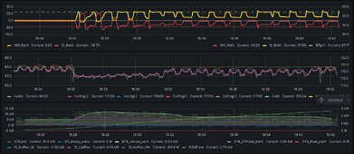
What do the SIs do when the GdCurNom is exceeded? It would reduce the battery charging, I guess, that's all the inverter can do. No, I guess I forgot, that's a feature the manual describes. It does change direction and discharge the battery to not exceed the grid / generator limit. In the top plot, it came out of silent mode, so charging the battery voltage (yellow) to the target (dashed green). At the same time, the oven was in use, creating the square extra load in bottom plot about 1/min, and the stove top was probably in use also. The SIs alternate between charging and discharging during this time, InvPwr (blue bottom plot) and BatteryCurrent (red top plot) both go pos / neg, from 18:26 to 18:30. By 18:30, the load from the range has reduced enough that it doesn't need to discharge from the battery any longer. Wow, looking at the data for the range, yikes 8 kw, =33A@240v!! I think that was the oven plus two top burners. Fun!
1705205343311.png


1705206309300.png
 
Back
Top