


You are using an out of date browser. It may not display this or other websites correctly.
You should upgrade or use an alternative browser.
You should upgrade or use an alternative browser.
❓ TDT-BMS Wanted Feedback/Experience
- Thread starter Steve_S
- Start date
Hi. This is how I use Wi-Fi for Home Assistant.It took a while, but the effect was very good. My BMS via the rs232 connector connected to the rs232 ttl to uart converter. And further to esp32. I converted the esp32 software from seplos-bms. Here's your software:Hi, I am also using TDT 6022, could you please explain that how you have managed to get the data via wifi . Are you using Bluetooth to Home assistant or RS 232 to home assistant then WiFi from home assistant or any other method. Also please share the links if any. Thanks
https://github.com/syssi/esphome-seplos-bms/issues/71 . Look for the comment from February 3. There is a tdt-bms.zip file there.
When in doubt, ask.
brunopiras
New Member
Do you think it works well with a TDT BMS 16S?Hi. This is how I use Wi-Fi for Home Assistant.It took a while, but the effect was very good. My BMS via the rs232 connector connected to the rs232 ttl to uart converter. And further to esp32. I converted the esp32 software from seplos-bms. Here's your software:
https://github.com/syssi/esphome-seplos-bms/issues/71 . Look for the comment from February 3. There is a tdt-bms.zip file there.
When in doubt, ask.
Any advice to connect uart-to-ttl ?
Thanks
I don't understand.Do you think it works well with a TDT BMS 16S?
Any advice to connect uart-to-ttl ?
Thanks
You mean the cooperation of the Inverter with BMS-tdt.
Is it about the cooperation of esp32 software with BMS-tdt.
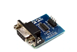
The RS232 connection is UART through such an adapter.
For me it's 14s, for 16s in the .yaml file remove # here:
# cell_voltage_15:
# name: "${name} cell voltage 15"
# cell_voltage_16:
# name: "${name} cell voltage 16"
Attachments
Last edited:
brunopiras
New Member
Hello there,I don't understand.
You mean the cooperation of the Inverter with BMS-tdt.
Is it about the cooperation of esp32 software with BMS-tdt.
The RS232 connection is UART through such an adapter.
For me it's 14s, for 16s in the .yaml file remove # here:
# cell_voltage_15:
# name: "${name} cell voltage 15"
# cell_voltage_16:
# name: "${name} cell voltage 16"
no it’s just about esphome and the TDT’s BMS, I’d been looking for something like that for a long time.
Hello there,
no it’s just about esphome and the TDT’s BMS, I’d been looking for something like that for a long time.
Attachments
brunopiras
New Member
Awesome..
about the rj11 (6 pin) of the BMS, what number of the connector can I use to uart-ttl ?
about the rj11 (6 pin) of the BMS, what number of the connector can I use to uart-ttl ?
middleAwesome..
about the rj11 (6 pin) of the BMS, what number of the connector can I use to uart-ttl ?
Attachments
brunopiras
New Member
nothing to do.. I think something is wrong..
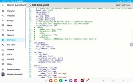
[08:22:05][W][tdt_bms:022]: Unhandled data received (data_len: 0x02): 25.01.46.42.E0.02.01 (7)
Editing the .yaml file. there is .yaml for two batteries.nothing to do.. I think something is wrong..
brunopiras
New Member
done! I've deleted the second part.Editing the .yaml file. there is .yaml for two batteries.
But same, enabled debug:
[08:29:39][D][uart_debug:158]: >>> "~25014642E00201FD30\r"
[08:29:39][D][uart_debug:158]: <<< "~25014642E00201FD30\r"
[08:29:39][W][tdt_bms:022]: Unhandled data received (data_len: 0x02): 25.01.46.42.E0.02.01 (7)
and if you have the switch set to BMS, on off off offdone! I've deleted the second part.
But same, enabled debug:
Attachments
brunopiras
New Member
?and if you have the switch set to BMS, on off off off
The switch?
take a photo of the bms where you have rj11?
The switch?
how did you connect rj11 to esp32
brunopiras
New Member
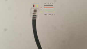
Esp32 ---> ttl<-->uart--------------------------------------------------------------------------->RS232

ADS 1 onEsp32 ---> ttl<-->uart--------------------------------------------------------------------------->RS232
View attachment 204514
brunopiras
New Member
I did!ADS 1 on
I've change a new esp32 and uart-to-ttl, I think during my last connection I've burn the ttl converter, otherwise done!!!
Thank you so much.
Just the last one.., there is no switch entity CHG MOS and DSGg MOS ?
Thanks
TechMaster_Sree
New Member
Thanks I will check it out. I have also noticed that after few cycles the FCC (Full charge capacity) is incrementing in one BMS and decrementing in another one . did you experienced anything like thisHi. This is how I use Wi-Fi for Home Assistant.It took a while, but the effect was very good. My BMS via the rs232 connector connected to the rs232 ttl to uart converter. And further to esp32. I converted the esp32 software from seplos-bms. Here's your software:
https://github.com/syssi/esphome-seplos-bms/issues/71 . Look for the comment from February 3. There is a tdt-bms.zip file there.
When in doubt, ask.
TechMaster_Sree
New Member
did you get any solution for SOC problem. I also facing the same and reported to TDTCurrently the TDT6032 and TD6022 firmwares are OK. The BMS is fully functional even in parallel operation. The only problem I sometimes have is with the SOC calibration
TechMaster_Sree
New Member
I have tested the issue with almost 8 BMS and all of them have same issue
TechMaster_Sree
New Member
When I have tested with JUNCTECH KG110F Battery Moniter, there is a small difference in the volt and Amp may be that cause this issue. per day its reducing about 2.5A in one bms
brunopiras
New Member
Hello, everyone,
finally I can see what's going on in my battery pack, I noticed that the cells are not aligned in voltage, in fact I mounted a 1A daly balancer, I noticed though that in the BT application of the BMS (Bms META) there are some setting values that I don't understand, could someone kindly explain me what they are?
Thanks for your time!!
The BL threshold is when the balancer turns on so in your example any cell over 3400mV the balance function for that cell will be open.BL delta cell is the deviation or difference between cells which in your example is set at 30mV.The balancer will work to get all the cells within 30mV of each otherHello, everyone,
finally I can see what's going on in my battery pack, I noticed that the cells are not aligned in voltage, in fact I mounted a 1A daly balancer, I noticed though that in the BT application of the BMS (Bms META) there are some setting values that I don't understand, could someone kindly explain me what they are?
Thanks for your time!!
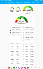
View attachment 210427
There is in the parameters a spot where you have Design Capacity,Full Capacity,Remain Capacity.Fully charge your battery dont worry about whether you charge to 3500mV or 3650mv just pick a mV,hopefully all you cells are decently balanced.When fully charged, Full Capacity is equal to Remain Capacity click W.Discharge the battery to a point your happy with 0% if you like but I dont like doing that.Charge your battery up and you will see your Remain Capacity climb up in Realtime Monitoring under DATA.When your battery is fully charged you will have a new Remain Capacity in Realtime Monitoring.Plug this value into Full Capcity and Remain Capacity in Parameters click W.If you have a real quality capacity tester like a ZKE that Andy uses in OFF GRID GARAGE you would just plug that capacity test value into Full Capacity and if fully charged Remain capacity would be the same and click W.IF not do what I did for a number of cycles and your SOC will become more accurate.So in my situation I have REAL QUALITY EV cells LF280K with like 314 or 315AH.So I guessed my Design Capacity was 300AH,Full Capacity 300AH and yeah I quessed that the remain capacity on my new cells was about 50%.When you charge it up the Remain Capacity will climb in my case it shot right past 300AH.Keep cycling keep plugging in the new values and click W and the Law of Averages will get you closer to your true SOC.Iam at about 314AH but it will come down a bit more but already Iam around the value of capacity for each of my cells.Not bad for a guessdid you get any solution for SOC problem. I also facing the same and reported to TDT
Similar threads
- Replies
- 34
- Views
- 5K
- Replies
- 6
- Views
- 2K
- Replies
- 60
- Views
- 3K