Gravity2424
New Member
I also posted this in beginners corner I hope that’s okay.
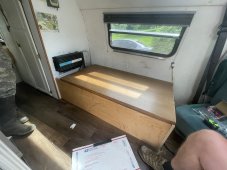
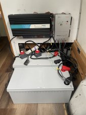
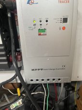
So my girlfriend and I bought a van and I’m fairly sure I got everything as far as the controller (EP Solar MPPT Solar Charger)/ inverter (2000 watt sure-sine wave) /solar battery (2 parallel 200Ah Renogy batteries) set up correctly. I’m now trying to hook up the 120v appliances to be able to use them on solar if we want to and I don’t want to mess anything up so that’s why I’m here.
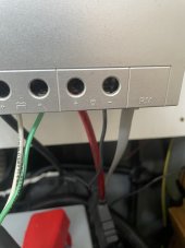
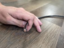
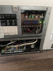
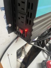
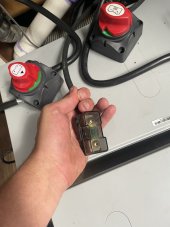
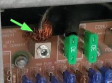
My understanding is that I need to hook a wire from my inverter to the correct hookup in my fuse box (see pictures) and it’s as simple as that? I believe the original owner had a wire already running from the fuse box to where our batteries are. This connection is what you see in the photo with the green arrow. I plan on cutting that wire and stripping it so it isn’t so frayed and then with the other end, should I put a kill switch in the wire and just use an eyelet to connect it to the positive on my inverter (end of that wire is the photo of it in my hand)? Sorry about the wires being kind of a mess, there is a method to the madness.
Lastly, I have a faint light coming on my inverter when I switch it on that says short circuit and I cannot figure out where it could possibly be coming from and I’m sure that isn’t safe if I’m trying to hook 120v up through it.
Also if you have any comments about the rest of the system would love to hear it, no experience whatsoever with any of this I would love to have any suggestions. Thanks!
So my girlfriend and I bought a van and I’m fairly sure I got everything as far as the controller (EP Solar MPPT Solar Charger)/ inverter (2000 watt sure-sine wave) /solar battery (2 parallel 200Ah Renogy batteries) set up correctly. I’m now trying to hook up the 120v appliances to be able to use them on solar if we want to and I don’t want to mess anything up so that’s why I’m here.
My understanding is that I need to hook a wire from my inverter to the correct hookup in my fuse box (see pictures) and it’s as simple as that? I believe the original owner had a wire already running from the fuse box to where our batteries are. This connection is what you see in the photo with the green arrow. I plan on cutting that wire and stripping it so it isn’t so frayed and then with the other end, should I put a kill switch in the wire and just use an eyelet to connect it to the positive on my inverter (end of that wire is the photo of it in my hand)? Sorry about the wires being kind of a mess, there is a method to the madness.
Lastly, I have a faint light coming on my inverter when I switch it on that says short circuit and I cannot figure out where it could possibly be coming from and I’m sure that isn’t safe if I’m trying to hook 120v up through it.
Also if you have any comments about the rest of the system would love to hear it, no experience whatsoever with any of this I would love to have any suggestions. Thanks!
Attachments
-
 954E9468-42C0-41A4-9069-925BA86B428C.jpeg196.7 KB · Views: 4
 -
 900A7CAB-7F45-4528-A040-18506193B068.jpeg104.8 KB · Views: 5
 -
 47F41116-27D2-4C1A-BA3C-B97001B45309.jpeg115.9 KB · Views: 6
 -
 86D005EC-2D9E-464F-878B-BE244D3D1400.jpeg152.2 KB · Views: 6
 -
 D9F0CD8B-4D37-4BEA-8E93-1BFBAE6CF6FF.jpeg149.3 KB · Views: 6
 -
 84648CE2-1647-4C02-8535-54EE06807DF5.png187.2 KB · Views: 4