diy solar

diy solar

12V 280Ah LiFePo4 battery Build and Test

You are right.
I just don't trust the specs on the blue aluminum case prismatic cells. Glad to be wrong but I gotta call it like I see it.
I learned a long time ago not to trust the spec sheet of just about everything.......especially alternative energy equipment!!
 
I think that the truth lies somewhere in the middle. I don't think its fair to call using the battery at or near its rated limits "abuse" but I do think that its not ideal and leaves little margin.

Correct me if I'm wrong but I don't believe there is a magic C-rate above which your batteries are quickly and irreparably damaged and below which you are safe. I believe bulging batteries come from poor cells, overcharging or a combination of the two.

That said, most manufacturers reccomended C-rate is 0.5c, 0.3c, or 0.2c and I agree with you that its best (and usually not difficult) to design for much lower C rates.

Furthermore, the max continuous C-rate is relative to temperature. Some datasheets will have a table showing max continuous charge rate at different temperatures. Battery life will be best at lower c-rates. Here is an example from CALB:

View attachment 19346

On the other hand, if EVE says their cells can handle 1C, the included busbars should be bale to support 1C (or greater). If anything is a design failure I would say its this (though its an easy one to fix).
I can't disagree. Maybe abuse is a little strong if a word, but you get my point.
I do have to disagree about the bus bars i received with mine. They were only about 0.090 thick and were not even as wide as the terminals. No way they make it to 200A.
 
Hi there,

I received yesterday 8x LF280 cells I ordered 7 weeks ago from UNIS. The packages arrived via train to Poland, final delivery was made by UPS per truck to Germany. The price was USD 1000 all in.
www.alibaba.com/product-detail/3-2v-280A...ery_62383387943.html

I´m installing the cells into a Sevel build Campervan (Jumper sim. to Ducato/Boxer/Relay/Promaster/Manager) under the driver seat.
The final setup looks like this:
2020-06-18 12_20_51-Window.png
The cells were well packaged, new, have no dents or scratches on the outside, and comply regarding weight and dimensions with the EVE LF280 specs. The 2D-Code systematic corresponds to EVEs spec sheet. The Voltage is 3.3V on every cell - so far so good.

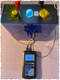
But, by measuring the internal resistance using a YR1030+ meter I get values of around 2.1mOhm on every cell (setpoint is <0.25mOhm).
L6.png
Any suggestions?

Thank you,
Mat
 
Last edited:
...solution found - after pressing the HOLD ZEROR button ZR appears in the display. Now all cell measurements are within 0,25mOhm...
L7.png
see also the video at Alibaba
 
Good idea, thanks a lot!

I was checking today the 2D-Codes at the cells. One was made at another factory, 3 were produced the same day. Maybe that's something I would ask for the next time I buy - would be nice all cells would come from the same batch...

By the way - Specification Code 66 if have seen here in other posts - guess that was the version before the LF280N ?
LF280 Codes.pngLF280 Cells.png
 
Last edited:
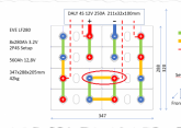
May want to add another busbar between cell pair 2 and 3 as shown in the red circle

View attachment 19378View attachment 19378

It depends on your current levels and busbar resistance, but adding that second busbar gives the upper cell in each 2p group a lower total resistance path. So that cell will supply more current. With a single busbar on the lower position, both cells in the 2P group have balanced resistance paths, and should share current much more equally at high rates.
 
I did some calculations on the bus bars last night and my 1/4" X 5/8" aluminum is good to 101A.
That is more than enough for this application, so I'm going to run with it.
If I move to a 12V 560Ah setup I'll probably move up to 3/4" wide 3/8" thick for 180A capability.
 
...just doing the same, based on Cu and metric ;)
I come up at 190A with a 16x4mm Cu bus bar - the 180A bus bar size above looks massive to me, even on base of Al

To tie the bus bar I plan like that:
bus bar.png
I plan to use vaseline on the pole and Loctite 243 at the thread. Comments welcome :)
 
Last edited:
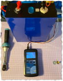
I would be reluctant to put any version of a thread locker on a bolt that goes into a battery terminal. For starters, it's going to throw off the already miniscule torque setting. Plus, should you need to remove the bolt it may require more torque than the terminal can handle.
 
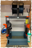
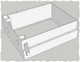
another thing I'd like to share is the housing for the LF280 4x2 pack I'm working on. It's modular and will be tied together using M6 A2 studs. This is the first prototype, final module will get a solid wall at the back (bottom of the picture). I'm sparing this for now, as the print time per module amounts already to 10 hrs ?
Case2.png
Case1.png
 
Last edited:
I would be reluctant to put any version of a thread locker on a bolt that goes into a battery terminal. For starters, it's going to throw off the already miniscule torque setting. Plus, should you need to remove the bolt it may require more torque than the terminal can handle.

The loctite shouldn't change the torque spec by much (it's not oil), and the torque is limited by the threads and not the terminal itself, by far.

But it's recommended to use studs instead of bolts anyway ;)
 
I am very familiar with galvanic corosion between aluminum and stainless steel, especially in moist environments. I will be using No Alox on the contact areas of the terminals and the buss bars.

I built an 8S battery using 90Ah Varicore cells and the copper bus bars and stainless screws the manufacturer.

I did not apply anything to the aluminum contact areas to the busbars not to the threads of the stainless screws.

Was this a mistake and should I disassemble and reassemble after adding No Alox?

This was less than two weeks ago and the battery has been unused since then, so I doubt there is any galvanic corosion yet, but if the battery will eventually develop corrosion at the Aluminum-to-Copper and/or Aluminum-to-Stainless and/or Copper-to-Stainless interfaces and No Alox can protect against that, I’d rather go to the trouble now...
 
another thing I'd like to share is the housing for the LF280 4x2 pack I'm working on. It's modular and will be tied together using M6 A2 studs. This is the first prototype, final module will get a solid wall at the back (bottom of the picture). I'm sparing this for now, as the print time per module amounts already to 10 hrs ?
View attachment 19723
View attachment 19724
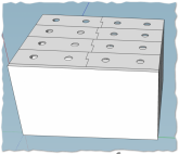
I would of love to see a rendering of your design, I'm not quite following it
 
Was this a mistake and should I disassemble and reassemble after adding No Alox?
I wouldn't worry about it unless you are going to use it heavily in a moist humid environment. I haven't done all 64 of of mine yet. I have a cell that may need swapping and I am slowly fabricating aluminum buss bars so I will do it over that project.
 
But it's recommended to use studs instead of bolts anyway ;)
Thank you. The main reason why I tend to use bolts is the way I plan to mount the moduls. Using bolts, I would use a torque wrench with a socket from the top through the holes of the case.

Using a stud, I would prefer to use an ISO 4026 / DIN 916 type and a hex bit from the top to hold it and an open torque wrench tool from the side to turn the nut (?). But this is kind of awkward because of the construction of the case (see picture).

What would be the main advantage / disadvantage to used studs instead of bolts ? Thanks for the help.
Case9.png
 
Last edited:
Back
Top