• Have you tried out dark mode?! Scroll to the bottom of any page to find a sun or moon icon to turn dark mode on or off!

diy solar

diy solar

147 volts dc will not pass thru breaker (yes, breaker is on)

mooseandbear

New Member
Joined
Apr 22, 2021
Messages
17
I have 6 160 watt panels that are wired in series. They are going to a 30 amp breaker as an emergency shut off. I can read 147 volts at the end of the wire during low sun but when I connect to a 30 amp breaker and turn it on, all I get on the other side is .5miliwatts. I have tried 4 breakers and they all do the same thing. My other side is 14 100watt panels wired in series/parr and they pass voltage (127 vts) thru the same breaker model just fine. The breaker is rated at 30 amps and 12-400 volts. I have no idea what is going on.
 
147V with open circuit, but 0V under a load?
It is time to trace each connection checking for voltage.

Connect the breaker, and the panels.
Check voltage from the panels, to the breaker, find where the voltage comes back.

Somewhere there is a bad connection, or the panels are bad.
 
Can you check IOC of each panel?

I have a clamp type amp meter test I can check check IOC with a connector that shorts both MC4 and an Anderson power pole for breakaway.

Even with my 24 volt 1200ah battery pack, there’s always more than 5 mW draw.
 
There is no load involved. I have 147 vts across the + and - wires going to the breaker, just like I have 127 vts at the wire ends going thru the other breaker that works. When I connect the 147 vt wires to its breaker, next to nothing comes thru. I have tried switching breakers with the same result. tried 4 breakers thinking a breaker was bad, no change. went back thru the panel wiring and it is straightforward + to - series connections thru out all 6 panels with a + and - coming out the end. should I disconnect one panel at a time and wire past it to test each panel separately?
 
That is correct. Panels to breaker-then thru breaker to long wire run to house. nothing at house yet, taking this one step at a time. Your question makes me think a shut off switch should be where the breaker is. I am using the breaker as an emergency shut off point.
 
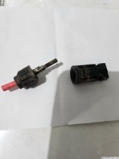
I had mine act like that and this is what was wrong.

mc4melted.jpg

Until I actually handled the mc4 connector I couldn't really see the damage.

Connecting just one panel from that array to the breaker and seeing voltage across it would kind of guarantee something like this is the problem.
Bit clunky but it would prove it basically.
 
Don't forget the connectors between the panels too.
If its a bad connector (corroded or burnt) you will see it when you disconnect them. The one in that picture actually broke in two when I touched it.
 
Folks, when you connect MC4 connecters together, it is always best practice to fill the contact space with dielectric grease to prevent water intrusion and help prevent rust/corrosion.

As for your connections, with your voltage, you will require a breaker rated for 300 volts DC and a DC disconnect switch rated for 500 or 600 volts DC.

For those people using even higher numbers of panels in series and reaching voltages above 300, then you will need 600 V DC rated breakers.
 
with your voltage, you will require a breaker rated for 300 volts DC and a DC disconnect switch rated for 500 or 600 volts DC
Very interesting about the voltage and breaker size. What is the source for this?

A google search for me turns up instructions on how to size a breaker for amps without mentioning how much to oversize for voltage.
 
Folks, when you connect MC4 connecters together, it is always best practice to fill the contact space with dielectric grease to prevent water intrusion and help prevent rust/corrosion.

As for your connections, with your voltage, you will require a breaker rated for 300 volts DC and a DC disconnect switch rated for 500 or 600 volts DC.

For those people using even higher numbers of panels in series and reaching voltages above 300, then you will need 600 V DC rated breakers.
My training states to coat the o-ring and mate area… not the electrical connection.
 
Crowz appears to be right on the money. I backed up the line and and finally got a negative side connector apart. testing with a breaker at that point showed all voltage passing thru fine from panels thru breaker. The connector on an extension cable from the panels to the breaker mounted at the end of the array looked corroded. I believe this is where the problem is located. I will change out the connector and test everything tomorrow.
 
Crowz appears to be right on the money. I backed up the line and and finally got a negative side connector apart. testing with a breaker at that point showed all voltage passing thru fine from panels thru breaker. The connector on an extension cable from the panels to the breaker mounted at the end of the array looked corroded. I believe this is where the problem is located. I will change out the connector and test everything tomorrow.
Yup, when something isn’t flowing energy, first thing to do is start tracing the wiring.
 
Very interesting about the voltage and breaker size. What is the source for this?

A google search for me turns up instructions on how to size a breaker for amps without mentioning how much to oversize for voltage.
The DC voltage rating label on the breaker.
 
My training states to coat the o-ring and mate area… not the electrical connection.
I said dielectric grease which is lubricant that conducts electricity. O-ring grease is a lubricant to keep the rubber O-ring from drying out and cracking and falling apart.
 
The DC voltage rating label on the breaker.
Perhaps I misunderstood what you were saying in an earlier post. I thought you were saying to derate a breaker by 50% when you recommended a 300 volt breaker for a 147 volt circuit.
I said dielectric grease which is lubricant that conducts electricity.
There are lubricants that conduct, but dialectic grease is not one of them. I am internet educated from sites like Motor Trend and perhaps they are wrong.

I do believe dialectric grease is a good practice to prevent corrosion for an electrical connection like a battery lug, but not because lobbing it on a gap will make something conduct better.
 
Folks, when you connect MC4 connecters together, it is always best practice to fill the contact space with dielectric grease to prevent water intrusion and help prevent rust/corrosion.
I've never seen any manufacturer recommend this. If their connectors was sealed, filling it with dielectric would leave no room for the mating connector. In reality, it will just smash out the extra and some of the air.
As for your connections, with your voltage, you will require a breaker rated for 300 volts DC and a DC disconnect switch rated for 500 or 600 volts DC.
At 147 volts, most would recommend something slightly above 147 volts. Maybe 10-20% not 400%
I said dielectric grease which is lubricant that conducts electricity. O-ring grease is a lubricant to keep the rubber O-ring from drying out and cracking and falling apart.
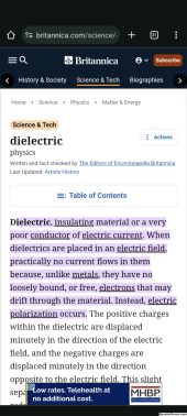
That's not what dielectric means.
The prefix di (or dis) means not.
Literally, an insulator.
Yes, it will help keep water out and prevent corrosion, but it's right in the name. It does not conduct.

Screenshot_20231113-194403.png
 
This is also why a commissioning step is very important; imagine if the connector was *mostly* working, just dropping say 30% of the voltage instead of all the voltage. In this case, you might not notice the problem, but if you had commissioned, you would have picked up that the current and voltage didn't match the expected values, and investigate.

Regarding the dielectric grease comment, you should probably only follow the manufacturer's installation procedures. None of the MC4's I've ever used require (or even allow) the addition of any sealant or insulator, but I will stand corrected if someone can point me to one.

And with MC4's, be wary of any internet "expert" that tells you to disassemble the connector and slide part of it onto the cable before crimping - I've never come across an MC4 manufacturer that teaches disassembly of the MC4 - this is a recipe for getting a seal pinched, water ingress, and connector failure.
 
original problem is solved. found a connector on a store bought extension cable was the problem. The metal was not fully inserted into the connector but far enough that when I put a probe lead in the connector, I could see the voltage, but when it was connected to its mate, nothing came thru. Thanks to all for the help. 1additional question, does any company make a charge controller that has a 48 volt battery charger as a "backup" for cloudy days? Would like to find one that connects to 110 ac for a backup charger.
 
original problem is solved. found a connector on a store bought extension cable was the problem. The metal was not fully inserted into the connector but far enough that when I put a probe lead in the connector, I could see the voltage, but when it was connected to its mate, nothing came thru. Thanks to all for the help. 1additional question, does any company make a charge controller that has a 48 volt battery charger as a "backup" for cloudy days? Would like to find one that connects to 110 ac for a backup charger.
I know AIIMS makes one, but at 48 volts it only pushes about 13 - 17 DC amps. Not sure of your actual need. Also, I found with multi voltage chargers the amper age is listed for the lesser votlage and the higher voltage pushes less amps, but same wattage.

I found it hard to find 110 volt 15 amp chargers that push a lot of amperage to a battery pack. The max I'd expect a 15 amp outlet to pull hours on end is 12 amps which is 1.4 kW watts, and with some battery packs sitting at 5 kWh or 10 kWh, that'd take hours.
 
And with MC4's, be wary of any internet "expert" that tells you to disassemble the connector and slide part of it onto the cable before crimping - I've never come across an MC4 manufacturer that teaches disassembly of the MC4
+1
MC4's are designed expressly so you don't have to disassemble them
 

diy solar

diy solar
Back
Top