Hello , Do you have a digital energy meter to measure both the active power and apparent power ?
When there is grid power , the inverter just show the active power part of the grid import /export since the inverter will synchronize to the grid voltage , so if there is reactive power part , the inverter won't display it , you could see when the inverter works in power backup mode , there are Peps and Seps , both the active and reactive part are showing .
But the Amp meter could measure the RMS value without considering the power factor between grid voltage and current .If there is digital energy meter, you should be able to read the active power(P) and apparent power(S) directly .
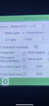
But if it is the CT ratio issue , you could be able to find it easily , you could check if the CT ratio configuration via inverter is same as the real CT ratio .