Hi all. It’s been several months since I posted my review of the 18KPV inverter entitled “My Experience with the 18K PV Part 1 https://diysolarforum.com/threads/my-18k-pv-experience-part-1.70933/
Sine that original post, the 18KPV continues to work with zero problems. As stated in my previous review, I have been using the 18KPV in lead acid mode with my DIY battery (a single 2P16S setup using 32 CATL 302Ah cells for approx 30KWh of capacity). This setup was being used with a Daly 500A BMS. The 18KPV in lead acid mode works flawlessly.
I had promised that my follow up review would’ve dealt with the 18KPV communicating with a DIY battery using Daly and the JK inverter BMS.
Well, there’s not much to say about the Daly. The Daly simply did not communicate with the 18K PV despite my best efforts and trying to get support from Daly. The Daly folks tried to be helpful but the Daly BMS just wasn’t doing it. I’m sure there is someway for this to work with communication but that way simply escaped me. And what makes matters worse is that Daly provides almost non-existent useful documentation on their products. Even their youtube videos are not detailed enough for the DIYers.
I recently added an additional 30KWh DIY battery for a total of 60KWh capacity, so I now have 2x 2P16S DIY packs each with 32x CATL 302Ah cells.
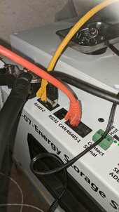
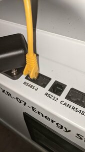
I have a 200A JK inverter BMS connected to each of the 2 DIY packs wired in parallel. The JK BMS simply worked…first time with no headaches. The 2 JKs in parallel works well together with the JK master doing all the necessary calculations for the entire battery bank and communicating that to the inverter.
The JKs are loaded with firmware version 15.17. In this firmware version I’m seeing LuxpowerTek being supported in addition to Pylon. I’m not sure if earlier versions had the Luxpower support but 15.17 certainly does. Both Luxpower and Pylon protocols on the JK work with the 18KPV, which is not surprising given that the 18KPV is a Luxpower device and Pylon is broadly supported by many different brands of inverters. For the 18KPV, I chose option 6 under Lithium when LuxpowerTek was selected at the JK and option 2 when Pylon was selected at the JK.
I was hoping that I would see individual cell information on the 18KPV screen or via the web portal but I am only seeing summary information in terms of total KWh capacity and what remains. The 18KPV also reports what the total charging and discharging maximums for both JKs and the amount of power currently being charged or discharged. Seeing the individual cell info on the inverter isn’t a big deal but it would’ve been nice. I’m not sure if the limitation is the 18KPV or the JK sending the information to the 18KPV or even if it’s at all possible.
I’m really happy with this 18KPV and JK combination. Next step will be to add Solar Assistant so I can have access to the JKs remotely. I got a bit spoilt with web remote access to the BMS when I was using the Daly with their wifi dongle. I think wifi is the only thing the JKs are missing. Other than that, the JKs are working really well.
Sine that original post, the 18KPV continues to work with zero problems. As stated in my previous review, I have been using the 18KPV in lead acid mode with my DIY battery (a single 2P16S setup using 32 CATL 302Ah cells for approx 30KWh of capacity). This setup was being used with a Daly 500A BMS. The 18KPV in lead acid mode works flawlessly.
I had promised that my follow up review would’ve dealt with the 18KPV communicating with a DIY battery using Daly and the JK inverter BMS.
Well, there’s not much to say about the Daly. The Daly simply did not communicate with the 18K PV despite my best efforts and trying to get support from Daly. The Daly folks tried to be helpful but the Daly BMS just wasn’t doing it. I’m sure there is someway for this to work with communication but that way simply escaped me. And what makes matters worse is that Daly provides almost non-existent useful documentation on their products. Even their youtube videos are not detailed enough for the DIYers.
I recently added an additional 30KWh DIY battery for a total of 60KWh capacity, so I now have 2x 2P16S DIY packs each with 32x CATL 302Ah cells.
I have a 200A JK inverter BMS connected to each of the 2 DIY packs wired in parallel. The JK BMS simply worked…first time with no headaches. The 2 JKs in parallel works well together with the JK master doing all the necessary calculations for the entire battery bank and communicating that to the inverter.
The JKs are loaded with firmware version 15.17. In this firmware version I’m seeing LuxpowerTek being supported in addition to Pylon. I’m not sure if earlier versions had the Luxpower support but 15.17 certainly does. Both Luxpower and Pylon protocols on the JK work with the 18KPV, which is not surprising given that the 18KPV is a Luxpower device and Pylon is broadly supported by many different brands of inverters. For the 18KPV, I chose option 6 under Lithium when LuxpowerTek was selected at the JK and option 2 when Pylon was selected at the JK.
I was hoping that I would see individual cell information on the 18KPV screen or via the web portal but I am only seeing summary information in terms of total KWh capacity and what remains. The 18KPV also reports what the total charging and discharging maximums for both JKs and the amount of power currently being charged or discharged. Seeing the individual cell info on the inverter isn’t a big deal but it would’ve been nice. I’m not sure if the limitation is the 18KPV or the JK sending the information to the 18KPV or even if it’s at all possible.
I’m really happy with this 18KPV and JK combination. Next step will be to add Solar Assistant so I can have access to the JKs remotely. I got a bit spoilt with web remote access to the BMS when I was using the Daly with their wifi dongle. I think wifi is the only thing the JKs are missing. Other than that, the JKs are working really well.