diy solar

diy solar

1st electrical system diagram - Van build

SpiritualRhino

New Member
Joined
May 27, 2021
Messages
4
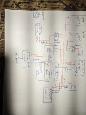
Hi all. After much research I have settled on this preliminary diagram for my build in a Nissan NV 2500. I know I have some more things to consider such as the length of the wires. I plan to have all the components in a box of sorts so the things that need to be close together will be. But as far as lines to the alternator or to the panels I may need different size wires as I figure that out. Just looking for some confirmation from people with experience that these pieces should work together in this way without issue.

Thanks for your time
 

Attachments

  • PXL_20220319_231351739.jpg
    PXL_20220319_231351739.jpg
    131.4 KB · Views: 19
Assuming its a 12 volts system.
Your 2000 watt inverter can draw... 2000 ac watts / .85 conversion factor / 12 volts low cutoff = 196.078431373 service amps
196.078431373 service amps / .8 fuse headroom = 245.098039216 fault amps.
Your sok battery is only rated for 100 amps continuous.
You need at least one more to handle the draw of the inverter.
Lets ignore the pure dc loads for now.

Ah yep that's exactly why I'm here! From your formula it sounds like if I stepped down to a 1000W inverter I'd be fine. All I really need it for is to charge a laptop. I've also heard about how you can direct DC charge one if it has a USB-C input (which mine does) so I'll be looking into that as well.
 
This busbar works well for the positive and negative busbars.
For the positive side use mrbf fuses on top of the busbar.
For the negative side use zcase fuses under the busbar.
For the battery use this with an mrbf fuse

Code:
legend {
    {} { functional block }
    nnn|NNN| { fused busbar position where nnn is wire size in awg and NNN is fuse rating in amps }
    nnn|UUU| { un-fused busbar position where nnn is wire size in awg }
    <-> { bi-directional current flow }
    -> { uni-directional current flow }
    <- { uni-directional current flow }
    dpst { double pole single throw breaker }
    scc { solar charge controller }
}
dc_domain {
    busbars {
        positive {
            002|UUU|<->200A_fuse<->battery
            006|100|<-scc<-dpst<-panels
            004|150|<-dc2dc_charger<-150A_breaker<-starter_battery
            006|100|<-ac2dc_charger
            004|150|->1000W_inverter
            006|150|->fuse_block
            016|001|->shunt_power
        }
        negative {
            002|UUU|<->shunt<->battery
            006|UUU|->scc->dpst->panels
            004|UUU|->dc2dc_charger->starter_battery
            006|UUU|->ac2dc_charger
            004|UUU|<-1000W_inverter
            006|UUU|<-fuse_block
        }
    }
}
 
Last edited:
You really don’t need 8 AWG wire for only 400 watts of panels. After the MPPT, the most you will see is between 24 - 28 amps, so 10 AWG would be good. Finding 8 AWG MC4 cables is difficult. If voltage loss is a factor, by all means, use the thicker cable.

You have a 30 Amp or 50 amp fuse on the solar panels, but 2 panels in series prbably makes around 10 amps, so a 15 amp would be better. Although Over Current Protection is not ecessary, you could use a Midnite Solar breaker prior to the MPPT and that would combine the switch and the fuse.. The actual size will be based off the panels ratings.

Everything off those busbars needs a fuse.

I used 4/0 cable for my 2000 watt 12 volt inverter and fused with 200 amps. That inverter also drew 1 amp an hour it was on. The idle draw on that, my strereo, and some other things added up and made my 200 ah useable more like 170 ah.
 
You do not need that fuse on the panel to CC. You have a switch, that is all you need.
The 4 awg to the inverter will smoke before the 200 ampere fuse opens.
Did you use a voltage drop table to determine all the cable's awg?
 
You could combine the 30 amp AC-DC charger and the 2000 watt inverter into a single unit, an inverter/charger.

You have a mix of brands in your design. If you go with all Victron equipment then you would need only one app on your phone to monitor the system. You appear to have a shunt in the design but you didn't say which brand. The Victron BMV-712 provides a display that is handy for a quick check of the state of charge, as well as other data points. The BMV-712 has a temperature probe. The temperature data will be shared with the other Victron devices.

While I agree with smoothJoey that the single SOK 200 Ah battery limits what your inverter could do, it doesn't mean that you can't use an inverter of that size initially. If you know that you're not going to be pulling too many amps then the 200 Ah SOK is a good first step. Once you add more AC loads to the system (that exceed the 100 amp maximum draw of the SOK battery), you can add a second battery.
 
My 2000w inverter pulls 150 amperes steady. Then there is a startup for a micro second.
 
Back
Top