diy solar

diy solar

240v Split Phase with 4x Victron Multiplus and/or Autotransformer?

AT does what it says it does!
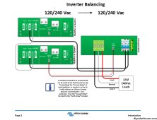
So in the example above, the iron and microwave are on the same leg/inverter? Second inverter is ‘helping’ via Autotransformer?

The other benefit is if one inverter fails you can hook up the AT in a stationary step-up config to still do 120/240, just less power.
 
Is that two Multiplus at 120V each in series, neutral doesn't go anywhere except each other?
If so, their current into AT has to be identical, and wattage will be same to the extent voltage output is same. AT has no ability to affect that.

4827W / 120V = 40A, hope that is at least distributed 34A/6A between L1/L2 so as to not overload auto-transformer.

Can you measure and report neutral current?


If inverters are 120V each and in parallel, they should match to within resistance match of wires and internal circuit resistance.
Think he’s set MPs up in split phase, his original post Option A. Trying to figure how this runs with AC passthrough IMG_3818.jpeg
 
Last edited:
If connected to grid or other source with N-G bond, I'd want to pass that neutral through to load. No need for autotransformer while passing power through.

With no external source, unbond at inverter and use auto-transformer to derive a neutral would be fine.
But if inverters are stacked for 120/240V, I don't think using auto-transformer instead of the neutral from inverters helps. Would only make sense for a 240V only inverter.
 
So in the example above, the iron and microwave are on the same leg/inverter? Second inverter is ‘helping’ via Autotransformer?

The other benefit is if one inverter fails you can hook up the AT in a stationary step-up config to still do 120/240, just less power.
Yes that's correct, the AT splits the load between the legs so the two MPs are outputting the same power (within the range of the neutral which is 28a, outside of that the MPs will go out of balance, but it still makes a huge difference). And yeah I was thinking the same thing!

Is that two Multiplus at 120V each in series, neutral doesn't go anywhere except each other?
If so, their current into AT has to be identical, and wattage will be same to the extent voltage output is same. AT has no ability to affect that.

4827W / 120V = 40A, hope that is at least distributed 34A/6A between L1/L2 so as to not overload auto-transformer.

Can you measure and report neutral current?


If inverters are 120V each and in parallel, they should match to within resistance match of wires and internal circuit resistance.
If connected to grid or other source with N-G bond, I'd want to pass that neutral through to load. No need for autotransformer while passing power through.

With no external source, unbond at inverter and use auto-transformer to derive a neutral would be fine.
But if inverters are stacked for 120/240V, I don't think using auto-transformer instead of the neutral from inverters helps. Would only make sense for a 240V only inverter.

Correct, it's wired just like posted above by ChrisG. I'm not sure how to go about measuring neutral current...

@WolfbaneAries Can you tell us how you have the AT connected to your inverters and if you ever pass through any AC-In power?

I'm off-grid so no grid connection, but when using a generator with the MPs in split phase, the generator can only supply power through one MP, the other one ignores the AC input and supplies 120v 180* out from the DC bus so as to maintain the split phase. So when I run on generator only, no solar, the power from the generator goes to MP1, out through the MP1 output, and then MP2 takes the power being supplied from the MP1 charging circuit (and/or the batteries if more than 35amps) to create the second leg of split phase.
 
If connected to grid or other source with N-G bond, I'd want to pass that neutral through to load. No need for autotransformer while passing power through.

With no external source, unbond at inverter and use auto-transformer to derive a neutral would be fine.
But if inverters are stacked for 120/240V, I don't think using auto-transformer instead of the neutral from inverters helps. Would only make sense for a 240V only inverter.
Slightly off-topic:

I’ve got a similar setup (but I’m on-grid) and I decided to do the unthinkable, and actually SWITCH my panel neutral from the quattros to the autotransformer neutral, but only when inverting. I get no leg balancing normally, even though the 100A Autotransformer is still connected.
In this case, the AT is just a disconnect that draws some negligible power.

When inverting, both legs balance beautifully, and I get full benefit of the two quattro 5ks.
The relay switch time is < 20 msec, so there is no missing neutral. This is critically important.
I use external ground relay 27V to activate the neutral switching relay, not as a “ground relay” at all.

Why go through all this? I have dedicated critical load panels, but i cannot separate the neutrals.
Connecting the AT neutral to the house neutral does wacky balancing all the way back to the utility transformer.
I didn’t want that.
 
Last edited:
I'm not sure how to go about measuring neutral current...

Clamp ammeter. Or current transformer connected to DMM. The ones I've got have a resistor internally and output something like 0.333V at 100A.

Yes that's correct, the AT splits the load between the legs so the two MPs are outputting the same power (within the range of the neutral which is 28a, outside of that the MPs will go out of balance, but it still makes a huge difference). And yeah I was thinking the same thing!

Correct, it's wired just like posted above by ChrisG.

What does the auto-transformer accomplish, that you wouldn't get just by using the neutral between the two inverters?
 
Clamp ammeter. Or current transformer connected to DMM. The ones I've got have a resistor internally and output something like 0.333V at 100A.


What does the auto-transformer accomplish, that you wouldn't get just by using the neutral between the two inverters?
The autotransformer allows one to extract the maximum wattage out of the stacked inverters, regardless of imbalance between the legs (up to 28A imbalance). Without it, each leg is limited to the inverter power rating.
 
Last edited:
The autotransformer allows one to extract the maximum wattage out of the stacked inverters, regardless of imbalance between the legs (up to 28A imbalance). Without it, each leg is limited to the inverter power rating.
This. I was doing a lot of swapping breakers around trying to balance out the loads so as to not put too much strain on one inverter. The real limits of my system were found this summer when trying to run the A/C in my camper while other loads around the property were being put on the system. Only by dedicating one entire leg to the camper could I run the A/C, and then everything else ended up on the other, causing a few overload shutdowns.

Today with the AT balancing the loads I was able to run the a/c, iron, and microwave all at the same time with no problem.
 
And what is the inverter power rating?

Now divided that by voltage and express in amps.
In my case I have stacked quattro 5kva inverters. They will each typically be able to do 4000W continuous.
So 4000W on L1, and 4000W on L2 (both inverters used for 240V loads).

The Autotransformer allows one to move wattage from one leg to another.
So i can use my 8000W of total inverter power on either leg (as long as the 28A limit is observed).
28A continuous x 120v = 3360W which can be transferred between legs if necessary (ignoring power factor for this discussion).

{incorrect example deleted}
The difference in power consumed on L1 and L2 must be less than 3360W (28A continuous).

So, for example, L1 can draw 5000W and L2 can draw 1640W.
From the inverters point of view, each is giving (5000+1640)/2 = 3320W
I have never hit the 28A limit because I balanced my panels anyway.

But i have tested it extensively with 1kW heaters, griddles, and microwaves all on the same leg.
It works spectacularly well.

For @WolfbaneAries , his multiplus-ii 3000kva stacked inverters will never hit the 28A, for continuous loads.
Maybe for surge loads.

In general, having an autotransformer balancing with stacked inverters doubles the available surge power for 120V loads, because you can draw from both inverters.
 
Last edited:
My math says 4000W / 120V = 33A continuous imbalance you could have supported if you connected neutral between the two inverters to loads.

Instead, you use the autotransformer, so you can only support 28A continuous.

However, I think the combined surge rating of both inverters will be available to start a 120V load such as a motor. I think data sheet says 9000VA (for how long?) so 18,000/120 = 150A surge.

So in my case, I can run continuously on L1 using 7360W and L2 using 0W (or vice-versa).

That's 4000W from one inverter and 3360W from the other.

How is it wired to combine those?
Do you have neutral of auto-transformer connected to neutral between the two inverters?
Or, is autotransformer the only source of neutral?
 
My math says 4000W / 120V = 33A continuous imbalance you could have supported if you connected neutral between the two inverters to loads.

Instead, you use the autotransformer, so you can only support 28A continuous.

However, I think the combined surge rating of both inverters will be available to start a 120V load such as a motor. I think data sheet says 9000VA (for how long?) so 18,000/120 = 150A surge.


That's 4000W from one inverter and 3360W from the other.

How is it wired to combine those?
Do you have neutral of auto-transformer connected to neutral between the two inverters?
Or, is autotransformer the only source of neutral?

(Unique to me Wiring, somewhat off-topic:
When inverting (and only when inverting), my loads use the autotransformer neutral only.
When grid-fed, the loads use the neutral between the inverters instead.
The AT doesn’t give you this capability, I had to engineer it.
I have an unusual on-grid setup, see my earlier post above about switching neutral.
)

You must use the autotransformer neutral if you want balancing.
For on-grid, never connect the autotransformer neutral to the neutrals between the inverters, weird things happen.

For the off-grid original poster, he would use only the autotransformer neutral.
The neutrals between the stacked inverters is present, but not connected to anything else, as Victron recommends.
 
Last edited:
Wiring:
When inverting (and only when inverting), the loads use the autotransformer neutral only.

Then I stand by my math that 28A (continuous) is all you've got.

Try loading it with approximately 5400W, 45A on just one phase. That's half way between 28A and 7360W/120V = 61A

I think it'll trip.


When grid-fed, the loads use the neutral between the inverters instead.

The AT doesn’t give you this capability, I had to engineer it.

Looking at Victron's auto-transformer schematic (back when we were picking apart a different brand on another thread) it seemed to me the relay in it could be repurposed to support that.

Switching out the auto-transformer and using grid's neutral seems to be the best approach (or use isolation transformer.)
 
Then I stand by my math that 28A (continuous) is all you've got.

Try loading it with approximately 5400W, 45A on just one phase. That's half way between 28A and 7360W/120V = 61A

I think it'll trip.


Looking at Victron's auto-transformer schematic (back when we were picking apart a different brand on another thread) it seemed to me the relay in it could be repurposed to support that.

Switching out the auto-transformer and using grid's neutral seems to be the best approach (or use isolation transformer.)
Victron has a Ground-Neutral bonding relay in the autotransformer. The original poster should probably use that for GFCI reasons.
I have no use for it.

Trip is an interesting word. The 100A breaker on my AT is that big so my normal 240V loads can pass through. They sell a 32A version as well.
The AT breaker also trips if the thermal sensor inside exceeds a safe level. There is no 28 or 30A breaker internally AFAIK.

For the 5400W case, you are correct, and i’ve edited my post.
The difference in wattage consumed by L1 and L2 cannot exceed 3360W (28A at 120V) because the current flows through the windings.

For some applications, that limitation is enough to skip the autotransformer.
I’ve never hit the limit, even trying to, but ymmv.
Others on this site are having custom ones made that can do more current.
 
Last edited:
For the record, according the manual, the Victron autotransformer will actually do 32A of neutral current for 30 minutes.
Which is 3840W. I assume it overheats after that and trips the protection.
 
Trip is an interesting word. The 100A breaker on my AT is that big so my normal 240V loads can pass through. They sell a 32A version as well.
The AT breaker also trips if the thermal sensor inside exceeds a safe level. There is no 28 or 30A breaker internally AFAIK.

For the 5400W case, you are correct, and i’ve edited my post.
The difference in wattage consumed by L1 and L2 cannot exceed 3360W (28A at 120V) because the current flows through the windings.

For some applications, that limitation is enough to skip the autotransformer.
I’ve never hit the limit, even trying to, but ymmv.
Others on this site are having custom ones made that can do more current.

I may have thought at one point the third pole was a 28A breaker for neutral, but it is a shunt trip which throws the 32A or 100A breaker.
It would be possible to have a current sensor (implement electronic circuit breaker) in which case we would want to know the overload/trip characteristics. Simply a thermostat seems more likely. 24V so there is a power supply in there.

If I was the designer I'd be nervous about allowing 200A on neutral protected only by temperature sensor. Inner windings and wires could get quite hot waiting for the thermal delay getting temperature sensor hot. Single inverter wouldn't be a problem, but about ten, 5kVA inverters would be. Considering fast trip would only be by 100A breakers (about 500A at 240V for magnetic instantaneous trip, slower thermal otherwise), neutral could carry way more for some limited time, given enough power driving.

It is a transformer. Both windings carry the same current. A single 14A breaker on one winding would protect center tap to 28A. Also want the shunt trip controlled by thermostat for over-temperature.


I don't see any benefit to using it with stacked pair of 4kW 120V inverters except for greater instantaneous surge. It would decrease not increase the imbalanced 120V load capability.


Victron also offers isolation transformer, suggests to prevent galvanic corrosion of boats.

It is rated 230V, 32A. It has a soft-start resistor/switch (similar to precharge) so inrush of transformer doesn't trip breaker. It has 1:1.05 turns ratio.

Betcha' it is exactly the same transformer. When used with 120V per winding, it is nicely behaved, close to an ideal transformer. When used at 230V it is driven partly into saturation as is typical for transformers meant to be connected to grid, saving capital cost but drawing multiple amps of no-load current.


I’m paranoid about excessive neutral current as well so I put a double pole 30A breaker on the AT neutral. I use the second pole of the breaker to de-energize my neutral switching relay so i don‘t get a floating neutral situation. Plus i can use the breaker to defeat any balancing if I want to.
It might be better to do a 15A breaker, i‘ll recheck that. The reason for the 100A breaker for me is for when i am not using the AT neutral, so i don;t want a 15A inline.

good links, thank you
 
Last edited:
I think if you open neutral you need to trip the 100A breaker to prevent lost neutral. Maybe you can tap into the trip circuit.

The center tap should be able to handle ~ 30A, with each of the L1, L2 connections handling ~ 15A.

I think Victron's thermal protection is sufficient unless source can supply something like 100A or more for an extended time. One or two inverters won't, a bank of them could. Grid could, depending on pass-through OCP, but if neutral of loads is switched from transformer center tap to grid, not a problem.

I'm just curious about the certification testing. Not for direct connection to grid, but did they think through failure modes and try a bank of 10 inverters with one autotransformer?

Check what phase voltages it produces. Expecting +5% one leg vs. the other no-load, dropping to -5% full load.
 
Back
Top