diy solar

diy solar

24v to 24v 100A DC-DC solution sought

Seven30

New Member
Joined
Dec 31, 2020
Messages
90
Location
Central Texas
Looking for a 100am 24-24 boost/buck charger to solve a design problem. Ive found a Victron unit but its really designed for the smart alternator systems.
Anyone know of some hi amperage alternatives?

This bus has an oil cooled 250 amp alternator designed to run cntinuously at rated output during idle.
There are external programmible regulators for this alternator that support lifepo charge profiles so to leverage the alternator to the fullest I want to directly charge the lifepo bank. The lifepo bank consists of 16 280ah cells 2p8s configuration and should be able to safely consume alternator output so the issue is how to support the 100amp vehicle/chassis loads the AC system being the big consumer.
Sterling has some seemingly interesting units that might meet your needs. I was looking through their line of products, but wasn't particularly happy with the information disclosure on their spec sheets. They left me with questions I felt should have been answered. In fact, the spec sheets seemed more like marketing sheets.

What kind of bus do you have? What year? I'm interested in solving a similar problem, though trying to solve it less invasively.

I don't want to modify the alternator's operating parameters and the more I consider the problem, the more I lean toward isolated DC-DC chargers. I do not want a component failure to wreak havoc on the rest of the chassis systems. It just doesn't seem worth it.

I removed the chassis A/C system and most/all of the original house loads. so I have none of those loads to worry about. The alternator is plenty capable of handling my house load + a modest charge while going down the road (in addition to whatever solar provides).

My main hangup is the price and number of units I would have to purchase to reach the desired output.

Why are MPPT charge controllers less expensive than their non-isolated dc-dc charger counterparts?
 
In case youre not familiar with sterling:

 
Why are MPPT charge controllers less expensive than their non-isolated dc-dc charger counterparts?

Economies of scale? I dunno, that's the best I can come up with.

An MPPT doesn't seem like it would work in this situation. Doesn't it require an initial starting voltage 5 volts higher than the system voltage?
 
Economies of scale? I dunno, that's the best I can come up with.

An MPPT doesn't seem like it would work in this situation. Doesn't it require an initial starting voltage 5 volts higher than the system voltage?
I think most (if not all do). I'm not that intimately familiar with how they work, though. I've seen conflicting information saying this will or won't work in different cases.

I'm also convinced a PWM wouldn't work well, either. As far as I understand it, PWM's don't limit current, they limit voltage.

All of that said, I'm leaning more towards something that does galvanic isolation, anyway, and most MPPTs, as far as I know, don't do this.

This still doesn't explain why MPPTs are lsss expensive than their non-isolated dc-dc charger counterparts, though. Frankly, since they're not a fixed voltage buck/boost converter, and offer the complexity of varying conversions from high voltage with an automated algorithm that tracks the input realtime, you would expect this technology to be more expensive. This leads me to call BS on the dc-dc charger market.

Would be interesting to see Will do a teardown on a non-isolated dc-dc charger vs an MPPT SCC.
 
Sterling has some seemingly interesting units that might meet your needs. I was looking through their line of products, but wasn't particularly happy with the information disclosure on their spec sheets. They left me with questions I felt should have been answered. In fact, the spec sheets seemed more like marketing sheets.

What kind of bus do you have? What year? I'm interested in solving a similar problem, though trying to solve it less invasively.

I don't want to modify the alternator's operating parameters and the more I consider the problem, the more I lean toward isolated DC-DC chargers. I do not want a component failure to wreak havoc on the rest of the chassis systems. It just doesn't seem worth it.

I removed the chassis A/C system and most/all of the original house loads. so I have none of those loads to worry about. The alternator is plenty capable of handling my house load + a modest charge while going down the road (in addition to whatever solar provides).

My main hangup is the price and number of units I would have to purchase to reach the desired output.

Why are MPPT charge controllers less expensive than their non-isolated dc-dc charger counterparts?
Its a 1964 GM 4106 parlor coach with the 50DN style alternator. The original AC is removed but Im planning on installing a modern system in its place although somewhat lower capacity. Originally the 4106 was 12v but I converted it to 24v. It was a big job with all the details but the large diesel cranks so much better with 24v system it was worth it. Now I have 24V@250amps available and want to make good use of it.
I could send the power to the house bank and use a 24-24 converter to keep bus charged but with the AC system it could pull a lot of amps.

Another idea that really isnt too far out is replace the FLA bus batteries with a medium sized LTO pack and use a solid state switch to supply for main house bank. The LTOs are nicely suited to cranking duty and can handle low temps. Cheaper than a large DC-DC converter i think.

Factoid: These old GMs once started need zero electricity to run which is kind of neat.
 
Sterling has some seemingly interesting units that might meet your needs. I was looking through their line of products, but wasn't particularly happy with the information disclosure on their spec sheets. They left me with questions I felt should have been answered. In fact, the spec sheets seemed more like marketing sheets.

What kind of bus do you have? What year? I'm interested in solving a similar problem, though trying to solve it less invasively.

I don't want to modify the alternator's operating parameters and the more I consider the problem, the more I lean toward isolated DC-DC chargers. I do not want a component failure to wreak havoc on the rest of the chassis systems. It just doesn't seem worth it.

I removed the chassis A/C system and most/all of the original house loads. so I have none of those loads to worry about. The alternator is plenty capable of handling my house load + a modest charge while going down the road (in addition to whatever solar provides).

My main hangup is the price and number of units I would have to purchase to reach the desired output.

Why are MPPT charge controllers less expensive than their non-isolated dc-dc charger counterparts?
Sterling and an interesting pro-split battery isolator however Im not sure if its designed for the lithium voltage range
 
Sterling and an interesting pro-split battery isolator however Im not sure if its designed for the lithium voltage range
It isn't (even says so). They also have what they call "alternator to battery chargers", also not designed for the lithium range. Not an issue for me since I only charge at the FLA range, anyway.

The whole zero electricity to run part is better than neat. That makes life so much easier to do as you wish with the electrical system.

At the end of the day, the most I really want is a current limiter and galvanic isolation from the chassis to the house system. Perhaps an inverter and AC to DC charger(s) should be on my plate for consideration. Absolutely inefficient power wise, but...why not?
I get the current limiter but why the desire for galvanic isolation between the two systems?
 
I get the current limiter but why the desire for galvanic isolation between the two systems?
Because I'm hyper-paranoid about burning up my alternator or something on the chassis circuit. My bus isn't as old as yours ('99), but I don't want to expose aged electronics to anything more than they're used to.
 
Because I'm hyper-paranoid about burning up my alternator or something on the chassis circuit. My bus isn't as old as yours ('99), but I don't want to expose aged electronics to anything more than they're used to.
Oh right, yours actually has a lot more sensitive systems I imagine. Is your chassis 12v or 24v?
 
Oh right, yours actually has a lot more sensitive systems I imagine. Is your chassis 12v or 24v?
24V. As is my installed house system. Some original house and dash systems are 12V. Not my concern though. I am and will only be tapping into the 24V chassis circuit.
 
Have you looked into any smaller DC-DC buck/boost devices that support parallel operation? I have some TDK Lambda I7C eval boards and they do offer a full-featured model which has a sync connection on the main board to connect all the parallel units so they sync their switching frequency across multiple units to balance load evenly and reduce noise... (according to my manual, the eval boards look like one might be able to remove a resistor to enable the sync function, on I7C models only)...

Here is some more info on paralleling I found on a quick search:


Paralleling also offers some advantages like load sharing which would provide better redundancy if units fail or whatever, since this solution would consist of more smaller units ganging up to hold the circuit.

These are the I7C boards I have (which are small, only 8a), but just posting it here for reference (since it would take 12.5 of them to get 100a):

Perhaps there is a suitable brand / model someone offers that is affordable, wouldn't require too many, and have a sync function to allow optimal parallel operation.

Just a different angle I am presenting out there to possibly consider...
This is good info. My first attempt at something like this was using cheap DC-DC modules I got for $35 a piece on amazon. I bought 5.

They claimed to be parallelable and claimed to be regulated. That was a joke. I followed all instruction for configuring and hooked up. Given the sketchy nature of purchasing electronics like this off Amazon, I didnt connect them all. I started with one. It was supposed to deliver 10-15A. It delivered anywhere from 20-30 from the start. Since I was letting the voltage pass-though, and they had cooling fans, I thought nothing of it. The current limiter never worked as advertised. I did try to adjust it down. I was brave enough to try 2 in parallel. I got 60 amps but that current only traveled through one of the circuit boards. Long story short, it popped. I chalked it up to lesson learned. Disconnected and tossed. Won't be using those, period.

I will do some research into tdk-lambda. They also have 12.5A models, I see. I could push roughly 10A at 27.2V. 8 of them would do what I want, though I could settle for 6.

I wonder if they have isolated models.

Thanks again. This may be the solution I was looking for.

I got my i7C08A-C03-EVK-S1 eval boards from Mouser and they shipped super fast. They look to be built very well, they do cost more than the Amazon / eBay ones, but I tested them out and I like them a lot so far.

I'm not planning to run mine in sync though, I just need them for POE supplies, one at 24v output and one for 48v output.

They are both buck and boost combined though, so you don't have to care about the input voltage as long as it is in range.

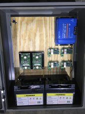
These are what mine look like (on left, on the black plate), I really like the nice solid input and output connector lugs on them, unlike the cheap ones come with.

1651462349315.jpeg
 
Last edited:
I got my i7C08A-C03-EVK-S1 eval boards from Mouser and they shipped super fast. They look to be built very well, they do cost more than the Amazon / eBay ones, but I tested them out and I like them a lot so far.

I'm not planning to run mine in sync though, I just need them for POE supplies, one at 24v output and one for 48v output.

They are both buck and boost combined though, so you don't have to care about the input voltage as long as it is in range.

These are what mine look like (on left, on the black plate), I really like the nice solid input and output connector lugs on them, unlike the cheap ones come with.

View attachment 93254
Whats the idle draw with these little boards?
 
Whats the idle draw with these little boards?

I'll see if I can check it soon when I get a moment... In the meantime, I found this info from Digikey's i7C description, saying that 5 mA is typical idle draw:

"With efficiencies of up to 97%, power losses are minimized, allowing the product to operate and deliver high useable power in demanding thermal environments. Under light load conditions, the i7C's control techniques significantly reduce power dissipation. A 5 mA input current draw is typical under zero load conditions. This can be reduced to typically 0.25 mA when the remote on/off is utilized to place the unit in standby mode, extending the amount of time battery-powered equipment can remain functional during periods of non-peak operation."

Ref:
 
I just noted though on their datasheet for the i7C, that technically they don't support 'Parallel Operation', so these may not work for that. The sync thing may be more for noise reduction only?

Might need to check some other model options out there. Or send them a query and ask if it can. I wouldn't want to buy some and then realize they wouldn't work for you.


1651541449470.png


But that first link I put above about the 5 things to know when running parallel...

...they referred to the following manufacturers (in bold):

"There are several commonly used techniques for load sharing in parallel DC-DC systems. One of the most common techniques senses the output current from each converter and compares it to the average, using current sense resistors, sensing amplifiers and a summing amplifier. The converters’ outputs are adjusted using trim or sense pins when necessary. Another popular method, the droop-share method, reduces the output voltage as a load current function if one converter produces more current than another. Power supplies such as Murata DBQ series and Ericsson PKM4817LNH module use the droop method to allow them to be operated in parallel."

Murata DBQ:

Ericsson PKM4817LNH:

(both of those state in the datasheets that they support parallel operation and use the droop method)
 
Last edited:
I wonder how these respond to over current conditions like charging Lithium chemistry. If they are constant current up to the voltage set point then running in parallel might work. Perhaps use an SBMS0 board to put them in standby until needed.
 
I wonder how these respond to over current conditions like charging Lithium chemistry. If they are constant current up to the voltage set point then running in parallel might work. Perhaps use an SBMS0 board to put them in standby until needed.

I would think they are like any other regulated power supply where it is CV only, and if the load is pulling the voltage down lower, the amps will just run max until the voltage is able to ever get up higher than the set-point, and the amps will pull back off...
 
Back
Top