diy solar

diy solar

buss bar recommendations for 8 DC to DC converters?

justinm001

Solar Addict
Joined
Dec 18, 2022
Messages
1,534
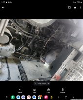
I have a 50DN industrial alternator designed to pump out 270a 24V continuously and is oil cooled. Currently disconnected but plan on connecting to my 24V chassis alternator (70a) and 24V starter battery system (4 12v batteries in series/parallel. This connects using a 2/0 gauge wire running 40ft from the rear of the DP engine to the front under bumper. The large alternator will be controlled with a wakespeed WS500 and will derate power if temps get high.

On top of this I have a 12V 10kwh battery bank for dc loads and aux house inverter as well as a 48v 10kwh battery bank powering the main inverter loads. I'm planning 9 total DC to DC converters since there doesn't seem to be anything larger. Since testing shows my alternators power shuts off when the engine is turned off I plan on using the remote disconnect connectors to 2 3 position switches, One All/Half/Off and other both/12v/48v. This would give me 9 options while driving incase i notice any decline in power and since I could be pulling over 4500w it could be taking 7HP from the engine, even though I have a massive engine it might affect going uphill. Also these chargers seem to put out a lot of heat so 8 might be a bit extreme. With the 2/0 existing wire I'll be right the 195a limit at 90c.

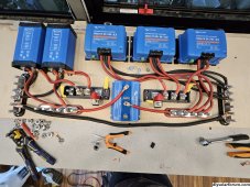
3x Victron Energy Orion 24/12-Volt 70 amp DC-DC Converter (2500w total 105a 24v 210a 12V)
5x Victron Energy Orion-Tr IP43 24/48-Volt 8.5 amp 400-Watt Isolated DC-DC Converter (2000w total 43a 48v and 85a 24V)

My question is what buss bar should I use for all of these? Ideally a lynx distributor but thats only 4 ports (5 or 6 if you use blue sea) and seems a bit of a waste to get 2 of them. I'd want fuses or breakers for all 8 plus something for the incoming power.

I was surprised how hot the 24/48v got when testing the 1 I have now. Would plywood be good enough for a base or should I consider some form of metal to act as a heatsink? My front bumper folds down and I have about a 2ftx6ft stainless steel floor space and about 2ft of height. Behind that is my 12V batteries and Quattro5000. The goal is to build it all on something removable so if I need to work on the 12v system I can just unscrew the board and remove the main wires to the buss bars and pull it out.

Should I set them all to the same voltage and what voltage should they be at?
 
Finishing up the build now, does everything look correct?

I have 2x 24-12v 70a (85a max) on the left then 3x 24-48v 8.5a on the right (waiting in 4th).

48v side is 6 gauge wire with 30a fuses and a 50a main fuse. 4 ga from argodiode.
12v side is 6 gauge in and 4 gauge out. 4ga from argodiode. 90a fuses and 175a main fuse
2ga ground between buss bars
2/0 main ground, alt input and outputs to battery banks.

The goal is to have this removable as batteries are behind. Also the possibility of enclosing it with fans in front and back.

Plan on wiring the remote ports to a cat6 keystone using cat6 cabling then can unplug a cable to make nice and easy. Plan on 2 3 position switches just unsure of wiring.

I don't have a fuse on the alt input or any inputs to the converters. Not sure if needed but can put a 200a on the argidiode input.

I don't think the argidiode is needed but I had a failed 24/12v orion before that was outputting 12v from out to in which energized the alternator and this could drain both banks. My alt is already wired to turn off when engine is off.
 

Attachments

  • 20231023_164305.jpg
    20231023_164305.jpg
    1.6 MB · Views: 32
When I build mobile electrical systems, I put a breaker in between each large source of sink of power and the bus bar when at all possible.

The reason is that the bus bar is now capable of pumping the full power of the electrical system - backwards - into the device. This far exceeds the capability of 2 awg wire.

An example breaker is this one:


This also makes it much easier to start up, diagnose, and do maintenance on a system.

I use bus bars with 2x the amp rating at least. When you dig deeper, the amp rating is often just the rating between 2 adjacent terminals.

In general though - concept looks good!

Will look more closely tonight at the details in your photo.
Thanks. I was planning on mbtf fuses or whatever they're called but the buss bar lugs are thicker. The agridiode is 160a rated per output but idk if that's the rating or if it'll blow like a fuse
 
What I do to help keep wires straight is to use color coded tape on them by voltage.

In DC, a common color coding system is:

red = 12 volt
blue = 24 volt
Orange = 48 volt

Officially, orange is for greater than nominal 48 volt system wiring, but I could not find anything official to separate 24 vs 48 volt DC in common use so I used orange as my default.

I also use yellow for solar (+) because it reminds me of sunshine but that is entirely my own random decision. :)

I put a piece of it at each end - really helps me stay organized and do changes in the future.

Just some decent colored electrical tape from the hardware store or you can be fancier as well.

Fuses are fine for safety, but there are useless for doing start up and maintenance of a live system.

Also - if your wife is out on the road alone and something goes wrong - mine will happily flip a breaker on / off to re-set something. There is no way that she is going to get out the wrenches and mess with a fuse. If that happens - it would be my fault for building it wrong. :rolleyes:
THANK YOU!!! I've been trying to think of a color coding and haven't seen one. I'll be adopting this everywhere. The chassis uses red or yellow cables if they're 12/24v but I can't remember which is which.

I still need to inspect my wiring from the alt to this panel as the alt power is turned off when key is off, but when I had a bad orion 24/12 it backfed 12v into the alt wiring which somehow turned on my basement lights. Good part is I know my basement lights aren't led and can run off 12v just dim as I've rewired them to use my house batteries now since I can finally replace with LED strips. There's a DC panel in bay1 which was mostly ripped out during an upgrade before me, but now I'm wondering if there's a relay in there for the alt, or maybe its on the battery side blocking output.

Its why I plan on putting dash switches since this is just alt charging I can just turn them all off completely and not use if any issues. Unfortunately my wife's too afraid to drive or use the coach alone so I'm the only one with it. We're slowly working on this hopefully, but so far we've swapped seats for a couple minutes a couple times on the freeway and once she drove it in the parking lot across the street.

Good luck with the wire color codes - it helps me a lot.

My youngest son helps me with mobile electrical builds and we needed a method that was intuitive for both us and the customers.

I spent more time on this wire color code subject than I care to admit. My original goal was to have a clear, defined color code setup that worked for having multiple DC voltages and 3 phase AC without confusion for systems that would be used in North America and the EU.

At this larger goal - I failed.

Taking it a bit further - I wrap my wrenches and sockets in electrical tape for safety reasons - but this covers up the size label.

Since one of the common arrangements in marine batteries is to use - 8mm thread for ( - ) and 10mm for ( + )

I wrapped the corresponding 13mm tools in black and the 17mm in red.

I try to not go overboard on this but it saves me a lot of time as I am a visual learner.

I will even put color tape on a wire every foot or so to make life easier for double checking things and reducing errors.
Here's my electricial bay door. I love how well they lay everything out. You can tell what I touched because it's not perfect.

Oddly enough yellow is 12v and red is 24v. What's really cool is every wire is numbered all over the wire and I'm sure there's diagrams in my paperbox full of manuals.

Here's what it looks like installed. Still need to wire the 4th 48v converter, and setup the big alternator. We're going to an auction in the morning then to cedar point in the afternoon so rushed this and at least I can get some power from the 70a alt for now. I just built a tile shower right above my generator so don't want to run it.

Used a network cable to a little 8 switch box so I can turn on 4 of the converters while driving and test to see how it affects my chassis batteries while driving.
 

Attachments

  • 20231027_151132.jpg
    20231027_151132.jpg
    1.9 MB · Views: 24
  • 20231027_151213.jpg
    20231027_151213.jpg
    723.8 KB · Views: 23
  • 20231027_151448.jpg
    20231027_151448.jpg
    1.8 MB · Views: 24
Over the weekend I tested it with an hour drive from home (full) to an auction, sat for a few hours then from auction (80% both banks) 2 hours to Cedar point for the day then 2 hours home. It was a rainy/very cloudy day so only got 1.1kwh of solar on 48v and maybe 200w on 12V.

While driving I played around with turning on the 3 48V converters and the 1 12V converter while only on my little 70a alternator. I noticed that the 48v converter which uses 17a of 24V would work fine when idling but when using 2 or just using the 12v (40a of 24V) it would overload my alt and the 24V voltage drops to 25V instead of the 28+ usually, but once driving I could easily run the 12V and at least 1 of the 48V converters.

I messed around a little with the voltage screw on a couple devices before leaving and noticed that it made a difference. For instance the 12V must be set low as many times it wasn't charging but was actually using the converter for power and the battery wasn't being touched. This happened around 16:30 on the graphs even showing the SoC levelled out and current around 0. One of the 48V was like this but the others must have been turned all the way up because they continued to charge the entire time. I was extra cautious as we were in a rush and didn't want to risk overheating the alt.

The next day I took it 30 minutes to my office and had all 4 converters turned on. Since I left full they just kept the batteries topped off and didn't use much power at all. Didn't have any high voltage issues which was my main concern.

All in all this made a huge impact and I have another trip this weekend that I plan on getting the wakespeed and other alt setup and working then this one disabled.
 

Attachments

  • 12bv.png
    12bv.png
    74 KB · Views: 1
  • 12soc.png
    12soc.png
    46.1 KB · Views: 1
  • 48soc.png
    48soc.png
    54.9 KB · Views: 1
  • 48vBV.png
    48vBV.png
    102.7 KB · Views: 1
When you get the big alt working that will really be the cherry on top.

Only thing i would add, and it may be of no concern at all, is that hooking some isolated dc-dc's to some non-isolated dc-dc's through a common ground connection may or may not have any benefit, and if it has no purpose, then the 'isolated' aspect of those dc-dc's is a 'wasted' upcharge. This is assuming they sell a non-isolated version at a cheaper price. Other than that, i have nothing to add, i think it's all pretty cool. :cool:
 
They don't make the non-isolated model for 48v so I was stuck using 2 grounds.

Spent a few minutes testing things before a long drive yesterday. The wakespeed can't seem to regulate voltage as it'll go up close to 30v then down to 24v every couple seconds. I'm assuming it's the long distance for the voltage wires. Was hoping it was bc I had to alts but unplugged the field on the other alt and same thing.

So I had a good idea and I unplugged the field on the 75a alt then wired the field to the 50dn and unplugged the wakespeed. It worked and I took a 4 hour drive yesterday. Issue is it was doing basically the same as the 75a alt where I can't seem to squeeze more than 1300w before my voltage drops on the dash and like 500w when stopped... so I was constantly turning on/off the converters while driving.

I'm assuming it must be the regulator that somehow limits the current. I have another 24v regulator so will try that before my trip back and see.

In this setup I don't really see the point in using the wakespeed as it doesn't provide any benefits over a stock regulator. I don't think the temp sensor matters since it's oil cooled so temps aren't an issue plus I'm wayyy under the max amps. It is nice I have logging of voltage and temps in victron with it though.

On my coach it idles low around 500rpm but I have a pto switch which will bring it to 1000rpm but doesn't do anything when in drive like at a red light so it's back to 500rpm. I need something foolproof that'll work at the low rpm as I don't want to mess with anything while driving.

I also got a red battery light on my dash which I need to track down. I only saw 3 wires on the 75a alt (24v, ground, field) and the regulator is all wired the same so not sure what's tripping that. I do have this odd t.t.l.t box that has a switch for alt1 and alt2. Once I switched it and got a red square on the dash.
 
Dug into it more and got it all figured out. My small alt has an internal regulator and apparently the big alternator had its old 24v regulator wired up next to the 12v but somehow disabled.

Ended up adding a new 24v regulator and setting all up. Alt runs a bit higher more in the 28-28.4V which seems safe still. Also the old alt (26si) is still running but I'm assuming isn't doing much of anything.

Took a 4 hour trip starting around 70-80% charge on both banks and the 5 converters worked perfectly. No issues with it pulling all the power while at a 500rpm idle. Just need to get the 6th wired up and I'll be golden.

I wish there was a way to turn off the 26si with a simple switch. Would love a switch to turn from alt1 to alt2.

Also see no point in having the wakespeed so likely gonna yank that
 

Attachments

  • Screenshot_20231113_142526_Photos.jpg
    Screenshot_20231113_142526_Photos.jpg
    640 KB · Views: 5
After some trips a few things I've noticed. The 12v system has no issues handling 1500w loads but doesn't really charge the batteries above 50%. The 48v charges closer to 80%. Both drop the charge wattage and I believe all converters are turned to max. Not much of an issue. Alternator has no issues pumping full wattage even at idle.

My 24v power turns on when ignition is on, not sure how this happens but makes it nice as I really don't need to use the switch.

But the problem is when I turn the key I like to wait 15-30 seconds to start, especially in the cold. This means my dc-dc converters are pulling power from engine battery. Is there anything I can use to delay them from starting for a minute? I figured I can use the 24v in power into some delay relay that'll turn on the switched relay on the converters.
 
A voltage sensing relay? So they only turn on when the alternator is running.
 
Back
Top