diy solar

diy solar

24V Van System Drawing. Get your overripe tomatoes ready!

The subject of earth ground vs chassis ground is complicated by the commonly used convention of indicating an electrical control enclosure chassis ground connection point with an Earth Ground symbol (like in the pic below). This is not technically correct, the box is not earth ground, the ground rod driven into the earth somewhere else is earth ground.

Well to me it means "connect this to earth". Like you write 12 V on something so people know they need to connect it to a 12 V source. But after doing a bit of research I see your definition est the correct one ;)


The Chassis Ground symbol is used to indicate connection to the vehicle's metal body and frame and the down pointed triangle is used for everything else related to DC negative.

This is what I would do too.

It's interesting to note KiCad uses:
- the chassis ground symbol for the ground symbol: GNDPWR
- the earth ground symbol for the ground symbols: earth, GNDREF
- the signal ground symbol for the ground symbols: GND, GNDA, GNDS
- a thick horizontal line symbol for the ground symbol: GNDD

It doesn't make a lot of sense but I've seen a lot of times the chassis ground symbol used to designate the power ground, and the earth ground symbol used to designate the signal ground in datasheets and schematics.

I mean, chassis ground symbol for the power ground, why not; but earth ground symbol for the signal ground isn't logical, they should use the signal ground symbol for that.
 
As for 'signal ground' and 'power ground' I'm unfamiliar with these terms.

The signal ground is usually a noise free ground used as the 0 V reference voltage for measuring and other sensitive components (for example it's where you would connect a voltmeter to display your battery voltage), while the power ground is used to connect all the high power components (like an inverter for example).

You don't want to mix the two types of components together because the first ones can be disturbed by the second ones.

On a car the power ground would be the chassis (where the alternator, starter, etc... are connected) while the signal ground would be the battery terminal (pretty much all sensors on a car have a dedicated ground wire going to the ECU, they're not using the chassis).

However, usually there's multiple signal grounds which uses the chassis for economical and practical reasons, but they chose strategic chassis emplacements for them (i.e. not in the middle of a high current path) and you still have star grounding after that (like the sensors having each their own ground wires and the ECU being the center of the star).
 
Last edited:
  • Like
Reactions: Dzl
The signal ground is usually a noise free ground used as the 0 V reference voltage for measuring and other sensitive components (for example it's where you would connect a voltmeter to display your battery voltage), while the power ground is used to connect all the high power components (like an inverter for example).

You don't want to mix the two types of components together because the first ones can be disturbed by the second ones.

On a car the power ground would be the chassis (where the alternator, starter, etc... are connected) while the signal ground would be the battery terminal (pretty much all sensors on a car have a dedicated ground wire going to the ECU, they're not using the chassis).

However, usually there's multiple signal grounds which uses the chassis for economical and practical reasons, but they chose strategic chassis emplacements for them (i.e. not in the middle of a high current path) and you still have star grounding after that (like the sensors having each their own ground wires and the ECU being the center of the star).
All grounds should end up tied together at a single point (busbar) and that point should be bonded to the battery negative terminal with a heavy gauge conductor. For example 3 ft of 2/0 AWG wire has 0.0002 ohm resistance. Passing 100A of current through that 2/0 wire will create a 0.02V potential between the battery and the negative busbar which is not going to hurt anything.

As long as you use star wiring, currents in one conductor can't cause disturbances in other conductors. The entire point of using a star wiring scheme is to control what wires current is flowing through.

Using the vehicle chassis to deliberately carry current is a very bad idea. This may have been a common practice in the past, but no automaker has done this in decades to my knowledge. The reason why using the chassis as a ground return path is a bad idea are multiple:
  • Makes electronics more vulnerable to RF interference and ESD
  • Makes high power circuitry more likely to radiate RF interference
  • Can cause corrosion in the body or chassis (current flow through dissimilar metals plus water = bad things)
  • Collision damage repair can result in erratic behavior (Bondo is a terrible electrical conductor)
There are very valid reasons to connect the negative bus to the vehicle chassis ground:
  • Prevent static charge from building up a potential between the DC system and the vehicle chassis. Not doing this results in getting shocked when you touch equipment which can also damage sensitive electronics
  • Provide a return current path to clear wiring faults by blowing the fuse or trip the circuit breaker if a wire gets shorted to the vehicle chassis.
 
Using the vehicle chassis to deliberately carry current is a very bad idea. This may have been a common practice in the past, but no automaker has done this in decades to my knowledge.

Well pretty much all grounds of all cars (even today's ones) are like that...

They're better than before because they use partial star grounding, etc... but you'll see only one wire on the battery negative and it goes to the chassis.

Of course all the other things you said are true, but economics play a big role for car manufacturers, so reality doesn't really follows the theory, sadly.
I am gobsmacked. Seriously, car companies are still using the chassis for current return? No wonder cars rust so fast. I am going to stick to signal processing where people use proper interconnects.
 
Yep, never saw one (not couting EV of course...) using something else than the chassis for the negative side so far ^^

They're more grouped grounds with partial stars (basically one for each electronic module) but they still go on bolts on the chassis.
 
Can you clarify what is meant by star wiring / star grounding?

Is this a term for basically running discrete/dedicated out and back wiring to a central point (busbar for instance). In contrast to 'chassis return' in a vehicle or a common return path in a circuit board or something?

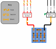
Conceptually like this, for instance?
Depiction of a star ground layout topology


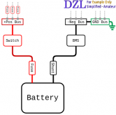
Would these be practical examples of star wiring:
a-basic-system-example-no-bms-core.png
Simplified-diagram-with-bms.png
 
Yes, all those are example of a star power distribution ;)

Yes, exactly; it means each component has its own wire to the power source, by opposition to daisy chaining for example.
 
  • Like
Reactions: Dzl
Using chassis ground is exactly the reason that trailer lights never work. When I replaced the lights on my utility trailer I searched until I found LED tail lights and marker lights for boat trailers that had a ground wire brought out of the housing. For the cost of an extra ground wire the length of the trailer (both sides) I have lights that I am confident in. Five year on, stored outside, no problem at all.

I like your circuit diagram, but agree with the other poster questioning using the load terminals of the SCC for your loads, I'd put those fuses on the battery buss bars.
 
Can you clarify what is meant by star wiring / star grounding?

Is this a term for basically running discrete/dedicated out and back wiring to a central point (busbar for instance). In contrast to 'chassis return' in a vehicle or a common return path in a circuit board or something?

Conceptually like this, for instance?
Depiction of a star ground layout topology


Would these be practical examples of star wiring:
View attachment 27458
View attachment 27459
Yes and yes.
 
  • Like
Reactions: Dzl
Updated yet again.

Realized I had left out the AC voltage and current monitoring Panel meter from the drawing. I also decided to replace the Daly's wimpy 6 AWG wires with 2 AWG wire. I know these wires are going to be really short, but seriously 6 AWG wires on a "150A" BMS?

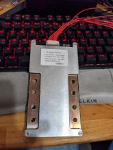
I just got a Heltec 8S 300A 3.2V/Cell BMS for my EVE 280AH LFP battery pack. Those Heltec guys are smart. There are metal plates soldered to each side of the PCB with 4 holes per connector (so I can bolt on 4 cables in parallel). I believe this BMS actually has pretentions of being able to handle its rated power levels. 300A working, 150A charging. Plus Cold temperature charging disconnect function also (although I will be using a BMV-712 which manages cold temperature charging shut-off as well as other stuff). Belt and suspenders man!!!

Heltec.jpg

Still undecided on which battery pack to use in the van. I am thinking about building a solar generator system for emergency backup. That might be a better use for the LiNMC cells. Still mulling my options. The van would have serious overkill from a power standpoint with a 7200 WH battery pack. That would power me for days without having to recharge. I could add a minisplit AC!!! Nah, not going to do that.
 

Attachments

  • VanPower12.pdf
    335.1 KB · Views: 20
  • Like
Reactions: Dzl
I like your circuit diagram, but agree with the other poster questioning using the load terminals of the SCC for your loads, I'd put those fuses on the battery buss bars.
The reason for putting the 24V loads on the SCC Load Output is the SCC provides a programmable low voltage disconnect for the load output and 20A is plenty for my 24V loads.

Side note, the SCC is capable of operating as a DC power supply without a house battery plugged in. This is important since I live in Phoenix and want the ventilation fan to run even if I have removed the battery pack during the summer months.

I have also been thinking add a voltage regulator to the loads output since I am thinking I might not want to put 29V (battery charging voltage) on my 24V loads. Still mulling the necessity of a 24V regulator over in my mind. I have found LED dimmers rated for 12/24V operation, but they are not rated for 29V (shortsighted cheapskates).

I hate value (crappy) engineering. I design devices that are spec'd to operate from 12 to 24V and they will operate normally up to 32V. Above that the overvoltage protective circuitry kicks in to disconnect the input supply (a PTC thermistor in series with a TVS) so nothing bad happens if you go higher than 32V. I test my systems by connecting them to a 48V power supply. This doesn't cause damage to my system or the power supply and normal operation resumes as soon as the overvoltage is removed. The actual input regulator circuit I use is rated for 36V.
 
I thought that may be the case - (low voltage disconnect) I too am concerned with that aspect. The possible solution that I came up with to get around over-discharging my cells is to use the SCC Load Output as a control signal to relays. Thus allowing the SCC to shut off loads without needing to run those loads THROUGH the SCC. This would even allow me to turn off high current AC loads without having to use high current DC contactors on the Inverter - simply by putting the relay on the AC side.

The inverter that I have does have low voltage cut-off, but it is pretty low, and it can't be changed. By letting the SCC monitor battery voltage and control the loads with a few milliamps on some quality relays, the system can turn off the 1500 Watt AC heater (or whatever it may be) when the bank voltage drops below the programmed min. As I understand it, most controllers have a different 'Low Voltage Reconnect Voltage' setting for some hysteresis. I have also read that some inverters don't like having the DC input getting shut off while under heavy load. Having the relays on the AC side is the same as simply turning off the load, which the inverter MUST be designed for anyway.

I'm curious as to your thoughts on this method.
My inverter a Victron Multiplus, has a programmable low voltage disconnect so no worries there. I an using a low voltage disconnect threshold of 24V which is about 10% SOC.

The 24V loads I am powering from the SCC load output probably total 10A. The SCC load output is rated for 20A.

The inverter is connected directly to the 24V bus.
 
I thought that may be the case - (low voltage disconnect) I too am concerned with that aspect. The possible solution that I came up with to get around over-discharging my cells is to use the SCC Load Output as a control signal to relays. Thus allowing the SCC to shut off loads without needing to run those loads THROUGH the SCC. This would even allow me to turn off high current AC loads without having to use high current DC contactors on the Inverter - simply by putting the relay on the AC side.

The inverter that I have does have low voltage cut-off, but it is pretty low, and it can't be changed. By letting the SCC monitor battery voltage and control the loads with a few milliamps on some quality relays, the system can turn off the 1500 Watt AC heater (or whatever it may be) when the bank voltage drops below the programmed min. As I understand it, most controllers have a different 'Low Voltage Reconnect Voltage' setting for some hysteresis. I have also read that some inverters don't like having the DC input getting shut off while under heavy load. Having the relays on the AC side is the same as simply turning off the load, which the inverter MUST be designed for anyway.

I'm curious as to your thoughts on this method.
The low voltage disconnect issue is what put me on the path that led to the Multiplus.

Xantrex makes a 24V 2000W inverter with a programmable LVD that I was looking at. It costs about $700. I finally decided I wanted shore power and once you add an AC charger and a transfer switch you are pushing $1000 which made the Multiplus comparable in cost.

At that point Victron seemed the best option for me.
 
I thought that may be the case - (low voltage disconnect) I too am concerned with that aspect. The possible solution that I came up with to get around over-discharging my cells is to use the SCC Load Output as a control signal to relays. Thus allowing the SCC to shut off loads without needing to run those loads THROUGH the SCC. This would even allow me to turn off high current AC loads without having to use high current DC contactors on the Inverter - simply by putting the relay on the AC side.

The inverter that I have does have low voltage cut-off, but it is pretty low, and it can't be changed. By letting the SCC monitor battery voltage and control the loads with a few milliamps on some quality relays, the system can turn off the 1500 Watt AC heater (or whatever it may be) when the bank voltage drops below the programmed min. As I understand it, most controllers have a different 'Low Voltage Reconnect Voltage' setting for some hysteresis. I have also read that some inverters don't like having the DC input getting shut off while under heavy load. Having the relays on the AC side is the same as simply turning off the load, which the inverter MUST be designed for anyway.

I'm curious as to your thoughts on this method.
To answer your specific question. I strongly suggest picking an inverter with one of the following:

A programmable low voltage disconnect threshold.
A switch (contact closure) input you can drive from an external low voltage detector device (like a battery protect).

The cheaper inverters, despite their claim of being "Lithium" compatible will drain your batteries totally flat (10V for a 12V version or 20V for a 24V version). Doing that repeatedly will shorten the life of your batteries. Considering how much batteries cost, the inverter seems an odd place to economize. Save a few hundred dollars on the inverter and get to replace $2000 worth of batteries early.

I can't afford to save money like that. :cry:
 
My inverter a Victron Multiplus, has a programmable low voltage disconnect so no worries there. I an using a low voltage disconnect threshold of 24V which is about 10% SOC.

The 24V loads I am powering from the SCC load output probably total 10A. The SCC load output is rated for 20A.

The inverter is connected directly to the 24V bus.
But therein lies the problem. Your inverter is on the battery buss. It happily draws power until the inverter low voltage shutoff kicks in. Perhaps your inverter is smarter than mine and that voltage can be adjusted. The fail mode I am concerned about here is relying on the humans to monitor the battery state when using AC power. The SCC is already monitoring the battery voltage but it does not provide a control signal. Furthermore my Giandel inverter does not have an input that can request an orderly shutdown. The workaround in suggesting uses commonly used relays to control the power consumption.
 
Actually the Xantrex Inverter I was looking at does have Shore Power. I must have been in a confused mental state, or else I must just really like the color blue.

The Freedom X is has both a programmable low voltage disconnect threshold voltage and you can also configure the ignition switch input to let an external device control the inverter.

It lacks the surge capability of the Multiplus (surge capacity is rated for 2 seconds vs 2 minutes), and it doesn't let you take advantage of the Victron ecosystem, but it is a very nice, mid-range priced inverter. By comparison the Chinesium dreck rates surge capacity in milliseconds which is a bad joke.

 
But therein lies the problem. Your inverter is on the battery buss. It happily draws power until the inverter low voltage shutoff kicks in. Perhaps your inverter is smarter than mine and that voltage can be adjusted. The fail mode I am concerned about here is relying on the humans to monitor the battery state when using AC power. The SCC is already monitoring the battery voltage but it does not provide a control signal. Furthermore my Giandel inverter does not have an input that can request an orderly shutdown. The workaround in suggesting uses commonly used relays to control the power consumption.
I looked at the Giandel and agree, you are kinda stuck. A contactor that can handle the current is not cheap and as you said, there is a risk using one will fry your inverter. If I was you, I would replace it while it is still working and get something better. You should be able to recoup at least half of the money you spent on Giandel.

I suggest you look at the Xantrex models I linked to. For some reason the 12V versions are cheaper than the 24V. If your system is 12V, you can get one of these for less than $600. These inverters are UL listed which is not a meaningless distinction.

 
Back
Top