• Have you tried out dark mode?! Scroll to the bottom of any page to find a sun or moon icon to turn dark mode on or off!

diy solar

diy solar

2P4S 280A build with JK BMS for sailboat

hwse

Solar Enthusiast
Joined
Jan 2, 2021
Messages
587
Well, I am committed. dreaming, plotting, planning no more. Let the building begin.
I finally did it. My LFP is on its way.
  • (
    ?
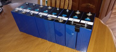
    EVE 280K (560A @ 12v) From Docan Power
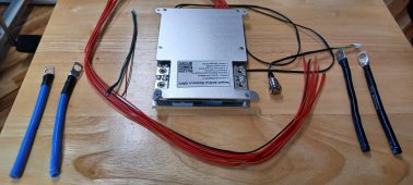
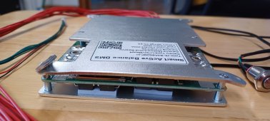
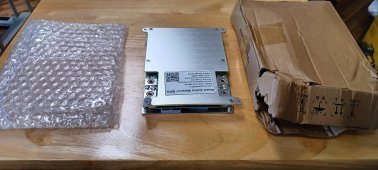
  • 4s JK BMS with 2-amp active balance and 200-A charge/discharge capacity (350-A surge for 5 minutes) from Henkzor
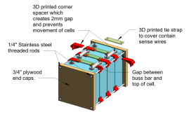
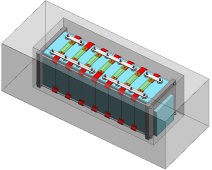
  • Flexible milti-thin plate buss bars for 2p4s configuration
  • 3d printed corner pieces to create 1mm space and secure the four corners form moving.
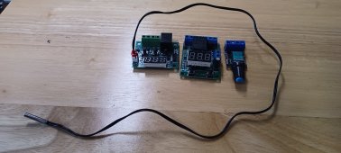
  • The bits and bobs to create the "a simple diy alternator charge system for lifepo4 batteries (12v system) on boats" from Wout Beekhuizen.
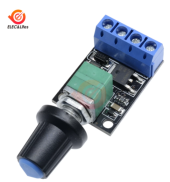
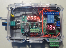
    • PWM controller to limit output
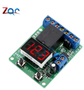
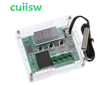
    • Voltage switch to turn on and off as needed.
    • Thermostat to shut down alternator if it gets too hot.
Now I just need to wait for the slow boat from China!
 

Attachments

  • LFP build.png
    LFP build.png
    175.6 KB · Views: 40
  • Papillon 2p4s.png
    Papillon 2p4s.png
    182.4 KB · Views: 39
I got the design for a simple DIY alternator charge system for lifepo4 batteries (12v system) on boats from one of my Facebook forums and it will cost $18 in electronics components and probably twice that amount for the plastic box and bits of wire to connect it. Still $35 isn't bad for a thermal protection external regulator.

It was designed by Wout Beekhuizen and does what it needed for charging LFP and nothing more. The problem with most regulators is that they are set up for LA and have 3-stange charging which is not good for LFP. With LFP, you want to charge it with CC to whatever you select as full and then stop charging. You also want it to not fry your alternator. His design does this and only this for about $15. It has a 12v switch to turn it on and off. A PWM to control the field strength to adjust how much current it puts out. It has a Thermostat mounted to the alternator that will shut it down if it gets too hot. A copy of it is in the files of the FB group "LiFePO4 Lithium Technical Discussions for Yachts" group.

I have my LFP and AGM start totally isolated from each other except for the battery combiner on the alternator outlet. The sense wire for the alternator will be on the AGM so that if the BMS shuts the house bank down, the alternator will still be connected to a battery and under the control of the regulator. I will charge to 14.0v and then shut off until the voltage drops to 13.2v. One thing that I might add to this very basic setup is a start delay with soft-start so that it does not kick in right away.
 

Attachments

  • PWM.png
    PWM.png
    219.8 KB · Views: 9
  • voltage switch.png
    voltage switch.png
    255.2 KB · Views: 7
  • t-stat.png
    t-stat.png
    294.7 KB · Views: 9
  • simple regulator.png
    simple regulator.png
    1.3 MB · Views: 10
I received notice that my (8) cells will be here this Friday. The BMS is scheduled for 6/18 and hopefully it will be close to on time. I am working on getting the corner pieces printed up and here is the first batch.

corner spacers.jpg
 
Second set of corner fixtures off the printer. I should note that these corner fixtures are not intended for compression but to fix the cells in place to prevent movement in any direction. The nyloc nuts will be snugged up just enough to remove any gaps between the parts.

fixture.jpg
 
I am using the 4s-8s JK BMS and it is the small cyan box mounted on the right end of the 2p4s model in Post #1. They have mounting holes in the case, and I will attach the BMS with screws to the end caps. At this time, I am hoping to make the end caps out or Starboard.
 
Hahah figured it was something like that. Figured they’d come up with a more creative name, oh well.
 
The cells showed up today and look great. Cell voltages of four were 3.32v and the other four were 3.31v. I modified six of my corner pieces to to also include a standoff to support an acrilic cover. It will be heat bent to an inverted "U" shape that will fit over the end caps and have support at the 1/4-points along the length. These supports are sized to hold the acrilyic at least 1/4" above the top of the posts. Papillon 2p4s covered.png
 

Attachments

  • Docan Power cells.jpg
    Docan Power cells.jpg
    196.9 KB · Views: 29
Im bookmarking this one
I plan to document each step to record how it goes. The only problem is that not much will happen for the next several weeks because it don't get the most important part (JK BMS) until 6/20/22. ?
Eventually I plan to add a Samlex EVO 1212HW inverter/charger to the system but that will have to wait for the boat kitty to rebuild.
 
I got the design for a simple DIY alternator charge system for lifepo4 batteries (12v system) on boats from one of my Facebook forums and it will cost $18 in electronics components and probably twice that amount for the plastic box and bits of wire to connect it. Still $35 isn't bad for a thermal protection external regulator.

It was designed by Wout Beekhuizen and does what it needed for charging LFP and nothing more. The problem with most regulators is that they are set up for LA and have 3-stange charging which is not good for LFP. With LFP, you want to charge it with CC to whatever you select as full and then stop charging. You also want it to not fry your alternator. His design does this and only this for about $15. It has a 12v switch to turn it on and off. A PWM to control the field strength to adjust how much current it puts out. It has a Thermostat mounted to the alternator that will shut it down if it gets too hot. A copy of it is in the files of the FB group "LiFePO4 Lithium Technical Discussions for Yachts" group.

I have my LFP and AGM start totally isolated from each other except for the battery combiner on the alternator outlet. The sense wire for the alternator will be on the AGM so that if the BMS shuts the house bank down, the alternator will still be connected to a battery and under the control of the regulator. I will charge to 14.0v and then shut off until the voltage drops to 13.2v. One thing that I might add to this very basic setup is a start delay with soft-start so that it does not kick in right away.
just be careful with those cheap electronics. they usually fail rather quickly.
 
I used that temp control and three out of four let the magic smoke out for no reason I could figure, I will be looking for something different before next winter.
 
My BMS and bits and bobbs for the regulator showed up today.
Unfortunately, the cover plate / heat sink was pretty mangled in shipping. Two of the mounting ears were bent with one almost 180º. Both the top and bottom plate are also bent outward between the case screws which seems to indicate that the FETs have probably been crushed somewhat.

Compared to the packaging that we get with the cells this was very weak. It was in a thin bubble wrap bag inside of a single layer cardboard box with the loose bits packed down around it. I have received $20 electronics that were packaged in solid boxes with form fitting foam over an inch thick inside. I expected better packaging than this.
 

Attachments

  • 20220621_100943.jpg
    20220621_100943.jpg
    285.5 KB · Views: 32
  • 20220621_100439.jpg
    20220621_100439.jpg
    270 KB · Views: 32
  • 20220621_100953.jpg
    20220621_100953.jpg
    210.3 KB · Views: 30
  • 20220621_104021.jpg
    20220621_104021.jpg
    125.3 KB · Views: 30
  • 20220621_104223.jpg
    20220621_104223.jpg
    346 KB · Views: 33
Holly hell, how could that tab be bent that much? I think what ever happened to cause that damage wasn’t going to be prevented by more cardboard.

Bummer my JBD 200a was also packaged in bubble wrap and cardboard box, but no play in the cardboard box.
 
I have been in contact with the Hankzor rep and they want me to test it to see if it functions but I am concerned about long-term health and hidden damage. I measured the two bend corners and they are both crushed 1.5mm and the center of that side is bowed outward 1mm. In order to do that, the outer two MosFET's on each side would need to act as a fulcrum to take the entire force required to bend the two plates.
 
I am thing about running (2) #2-AWG wires from the B- battery to the B- terminals on the BMS as shown by the two black lines. That route is the only one that I can see that will allow for large enough bends in the wire. It will cross over the buss bar so what precaustions should I look at to keep them from shorting?
 

Attachments

  • 2 awg neg.jpg
    2 awg neg.jpg
    298.3 KB · Views: 32
I just finished my first cruise with my new battery and it performed fantasticlly. Most days I motored for a couple of hours which brought the battery back up to full charge but on a couple of days, I had a bit of breeze so sailed with no recharge.
Inspite of having 6 of us aboard and using the deep freeze, 12v icebox conversion fridge and the hydronic heater a couple of times each day to get hot water we never dropped below 78% SOC
I am using my old Xantex InCharge for alternator regulator but have added a 1.0ohm 100W resistor to the blue field wire which limits the output to 60A. At that level with my fully sound insulated engine bay and no blower running, it ran at 95ºC to 95ºC which is ok given that my Ample Power alt is hot rated at 100ºC but higher than I like. I turned on the bilge blower which ends about 6" away from the engine bay the temp went down to 85ºC to 90ºC. I will be extending the duct to pick up air from the above the front of the alternator so that it pulls the heated air directly out of the engine bay which should also help a great deal. I also plan to add a 120mm pusher fan to increase the airflow to further cool it. With that I should be able to crank the output by another 20A.
 
I do not have any big draws, just a lot of long term draws in the 5-7 amp range. The main ones are:
  • Refer
  • freezer
  • hydronic boiler,
  • five +3A fans on heating system
  • autopilot
My daily usage is in the range of 125Ah - 175Ah so with the old 210Ah AGM. I needed to pull it down 80% and recharge fully each day which given their recharge rate is a losing proposition. I was constantly worried about SOC and would need to run my portable generator for 6 hour/day min to have any hope of keeping up. On this cruise, I never even started the generator and even on days when I motored very little, the SOC never dropped below 75% and I can safely take it down to 5% without any damage to the pack.
Looking forward to many days at quiet anchor.
 
After our first cruise with the new LFP battery we are thrilled. It was 6 days and 2-hours and during that time we did not give any thought to power conservation. We had the fridge, freezer, and all electronics running the whole time.
We used a total of 626 amps for an average of 102A/day. This is significantly less than we have used on any previous cruise in spite of adding the freezer. I have modified the AB icebox conversion from a mechanical thermostat to a digital that runs the compressor on low speed and eliminates the short-cycle that happens with the mechanical. I also added a much more efficient PWM controlled fan that both cools better and is completely silent. We also get a huge boost from the Peukert's ratio being 1.0 rather than the normal LA 1.25. We also get gains from the discharge voltage being 13.2v rather than 12.6 or lower for LA.
All-in-all, it comes to +30% gain in total efficiency.
 

diy solar

diy solar
Back
Top