


You are using an out of date browser. It may not display this or other websites correctly.
You should upgrade or use an alternative browser.
You should upgrade or use an alternative browser.
48v LiFePO4 build
- Thread starter JoeHam
- Start date

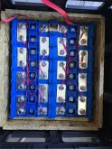
Progressing nicely.
Hoping someone can help me out here as this diagram has me confused. I will refer to the two black leads as that is my reference point to get the wiring done right.
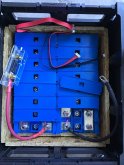
On page one you can see that the black wires go to cell 1 and cell 9. There is a mystery blue line between cells 8 and 9 which I assume is a busbar.
On page two you can see that the main battery posts are the negative of cell 1 and the positive of cell 16. That makes me wonder if they confused cell 9 and cell 16 between the two pages. I would guess that the black wires end up on the most positive and most negative terminals but cell 9 doesn't fit this assumption.
I have never used a BMS before so just looking for confirmation if anyone can help.
Attachments
OK I got this answer from Craig:
Really quick in the middle there are 2 wires one red and one black connected together. So the last red wire from first harness and black wire from second harness are connected together to same post.
So it looks like the directions are correct and I am back to assembling, thanks.
Really quick in the middle there are 2 wires one red and one black connected together. So the last red wire from first harness and black wire from second harness are connected together to same post.
So it looks like the directions are correct and I am back to assembling, thanks.
Stuck here until I can figure out how to get the Chargery to turn on. See here:

 diysolarforum.com
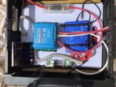
After that is sorted out I will wire up the Victron for solar panels and connect it to the battery.
The third level will simply be the inverter mounted on top of the whole thing.
Chargery Help Wanted
So I have hooked up my Chargery BMS 16t according to the supplied wiring diagram. It is my understanding that the unit should power up through the 18 wire harness I hooked up. I have tried with the unit switch on both the batt and ext positions without luck. I’m also not certain which...
diysolarforum.com
After that is sorted out I will wire up the Victron for solar panels and connect it to the battery.
The third level will simply be the inverter mounted on top of the whole thing.
Montana
New Member
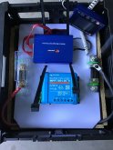
What’s that you have in the upper right corner of the Second level photo?And here is what the second level, mounted on a cutting board looks like
What’s that you have in the upper right corner of the Second level photo?
@Montana that’s the screen for the Chargery BMS.
I would not do an impact on any battery terminal bad advice!Will has talked about the terminals. They're M10 in metric bolt sizes and you can safely use a impact driver on them. I'd love to have them on my 280AH cells.
Similar threads
- Replies
- 8
- Views
- 423
- Replies
- 8
- Views
- 307
- Replies
- 6
- Views
- 169
- Replies
- 2
- Views
- 145