diy solar

diy solar

48v to 12v buck converter with common ground

RollingThunder

New Member
Joined
Feb 24, 2021
Messages
58
Hi all,
On my RV I have had my solar and 48v 280ah lifepo4 system with a Growatt running for a week now with no problems. The old 12v lead acid batteries for the engine and house are still in place. I plan to remove the old house battery, leaving only the engine battery.

For 12 volt charging/loads, the power goes from the Growatt to the old MagnaTek power box, where the AC is converted to DC and goes to the DC fuse panel. All is working well there, too.

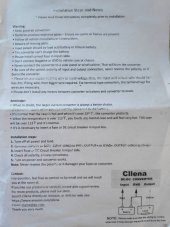
The next thing I want to do is use a 48v to 12v buck converter to power all the 12v devices directly off the battery. I bought a 60 amp 48v-12v converter, but the instructions state 'do NOT connect the converter ground to the chassis'. I assume that is because it has a common ground between the 48v and 12v side. It has only three terminals, the 48v pos, the 12v pos, and the common ground. The 48v system is not grounded to the chassis. It only exists between the growatt and the battery.

As a test, I disconnected the Magnatek's converter wires from the breaker to disable it, then wired the new converter to the posts which run to the lead acid house battery, to see if it would work. As I suspected, it did not, as the circuit is not complete, since the converter is not grounded to the chassis, if I am correct.

What can I do to make it work, other than running new ground wires from all devices back to a common ground for the buck converter? Is there some device I can use to allow the converter to connect to the chassis?
 
Is there a reason you do not want to ground the negative of the house battery to chassis? Was the old battery negative tied to the chassis?
 
If you mean the 48v battery, I didn't think it was necessary. Should I?
Yes, both the old engine and house batteries are grounded to the chassis.
 
If you mean the 48v battery, I didn't think it was necessary. Should I?
Yes, both the old engine and house batteries are grounded to the chassis.

Yes, I mean the 48V battery.

A couple of points.

The NEC considers a 48V system high enough voltage that it requires the DC to have a grounded conductor.
In a vehicle, things are not quite the same as in a stationary system, but I always recommend grounding the negative of a 48V system to the vehicle chassis. This ensures the DC circuit will not float to some arbitrarily high voltage with reference to the chassis.

Note: Other people have different points of view on this. They feel leaving the DC floating is fine.

BTW: Can you provide a link to the buck converter you have:

BTW2: Will there be any type of low voltage disconnect to shut off the Buck converter or are you counting on the BMS to do that?

BTW3:
For 12 volt charging/loads, the power goes from the Growatt to the old MagnaTek power box, where the AC is converted to DC and goes to the DC fuse panel.
Are you planning on replacing the magnatec or is the 48V buck going to be in addition to the magnatek. (I assume it is a replacement but want to be sure.
 
Yes, I mean the 48V battery.

A couple of points.

The NEC considers a 48V system high enough voltage that it requires the DC to have a grounded conductor.
In a vehicle, things are not quite the same as in a stationary system, but I always recommend grounding the negative of a 48V system to the vehicle chassis. This ensures the DC circuit will not float to some arbitrarily high voltage with reference to the chassis.

Note: Other people have different points of view on this. They feel leaving the DC floating is fine.

BTW: Can you provide a link to the buck converter you have:

BTW2: Will there be any type of low voltage disconnect to shut off the Buck converter or are you counting on the BMS to do that?

BTW3:

Are you planning on replacing the magnatec or is the 48V buck going to be in addition to the magnatek. (I assume it is a replacement but want to be sure.
Ok, I'll ground it.
Here's the new converter, 60 amp 48-12v.
I'll let the BMS handle the shutoff, where I raised the low voltage disconnect to 2.55, and lowered the hvd to 3.6.
The new converter will be replacing the magnatek.
 
So, what do do with the buck converter's ground? It says in the instructions NOT to, but the 12v devices won't have a complete circuit without it. Is there some kind of isolator or something I can put between the buck converter's 12v ground and the chassis to make it ok? I'm wondering if it has something to do with the alternator when the engine is running...
 
that does not make sense for a 3 wire buck converter. Could you please send a link to the instructions.
 
Perhaps they meant to the chassis of the buck converter itself. The converter ground lug would be isolated from the converter chassis unless the two became joined.
 
See attached pic of the instructions.
Yes, when I saw that I was pretty confused as well, it really threw a monkey wrench into the works. Maybe @CamoGreg is right.
 

Attachments

  • CllenaVoltageConverter.jpg
    CllenaVoltageConverter.jpg
    87.5 KB · Views: 15
That does not square with this line from the instructions:
View attachment 84343
Poor instructions for sure. How can either make a circuit if they just end.
Perhaps they want the negative going directly to a battery and not feeding current through the chassis....not using the chassis as a conductor.

I wonder in my drawing if I should bus the ground out of the converter and branch to both 48v and 12V neg bus bars?
Like this:

converter2.png
 
Last edited:
Poor instructions for sure. How can either make a circuit if they just end.
Perhaps they want the negative going directly to a battery and not feeding current through the chassis....not using the chassis as a conductor.

I wonder in my drawing if I should bus the ground out of the converter and branch to both 48v and 12V neg bus bars?
Like this:

View attachment 84344
That would still tie GRD to Chassis.

I wonder if the case of the converter is tied to either the 48V positive or the 12V positive? That would create a big danger of a short circuit if the GRD is tied to the vehicle Chassis. That is the only explanation for what the instructions say that I can think of.
I know a lot of heavy load 12VDC consumers don't like using chassis as a GRD conductor. Winches for example. They don't want a high amp load completing the circuit through the Chassis. Battery+ to battery- connections only. Appropriately fused.
 
Last edited:
I know a lot of heavy load 12VDC consumers don't like using chassis as a GRD conductor. Winches for example. They don't want a high amp load completing the circuit through the Chassis. Battery+ to battery- connections only.
I sure hope there's some way to make this work other than running new grounds back from every light, pump, etc all over the rig.
 
I sure hope there's some way to make this work other than running new grounds back from every light, pump, etc all over the rig.
Where were the Main POS and NEG conductors attached from the old converter? I'm sure you won't need to rewire all that. I've seen some where they simply insert a bus bar where the old house batteries used to be. Then connect the new converter to the new pair of bus bars.
 
Back
Top