diy solar

diy solar

80% rule on solar circuits?

Jet

New Member
Joined
Jun 22, 2021
Messages
118
I plan to use 450watt panels. I want to put two panels per string in parallel because I'm using Electrodocus. The runs will be quite short because it's a 12x16 ft cabin so voltage drop isn't that much of a concern. I was gifted a bunch of 10 AWG RMW-2 wire. It says the circuit protection should not exceed 30 amps.

Do I need to use the 80% rule on solar circuits? Panel IMP 13.16 A. 13.16 x 2 = 26.32 amps. So if multiplied by 1.25% we get 32.9 which is more than 30 amps. Would it be ok to use the wire and a 30 amp fuse or breaker? Our fuses able to handle currency exceeding 80% of they're ratings more than breakers? I realize the panels won't produce max amperage continuously or even on those days. As the solar panels degrade the max amperage will be lower. Thanks for your help.
 
Don't multiply by 1.25
Multiply Isc by 1.56, which is 1.25 x 1.25
The usual 25% for nuisance trips, and another 25% for cloud-edge effects (current higher than Isc.
It's in the NEC.

If using magnetic-hydraulic breakers, the first 25% extra might be reduced or eliminated.

What is your panel series/parallel configuration? No OCP required for 1 or 2 strings in parallel (but do consider whether they are electrically paralleled after home-run wire, vs. go to separate MPPT)
 
1S2P panel configuration. (Two panels that are in parallel there are no series connections). Not using MMPT. The positive of each string is connected to an ideal diode charge controller and the negative is connected to the battery. Each charge controller has two ideal diodes each taking one string/2 panels for a total of four panels on each controller. I'm using 6 awg wire from the controllers (with fuses) to the main PV positive bus bar. The 1/0 wire from positive bus to lithium battery has a class T fuse.
 
1S2P panel configuration. (Two panels that are in parallel there are no series connections). Not using MMPT. The positive of each string is connected to an ideal diode charge controller and the negative is connected to the battery. Each charge controller has two ideal diodes each taking one string/2 panels for a total of four panels on each controller. I'm using 6 awg wire from the controllers (with fuses) to the main PV positive bus bar. The 1/0 wire from positive bus to lithium battery has a class T fuse.
Don't multiply by 1.25
Multiply Isc by 1.56, which is 1.25 x 1.25
The usual 25% for nuisance trips, and another 25% for cloud-edge effects (current higher than Isc.
It's in the NEC.

If using magnetic-hydraulic breakers, the first 25% extra might be reduced or eliminated.

What is your panel series/parallel configuration? No OCP required for 1 or 2 strings in parallel (but do consider whether they are electrically paralleled after home-run wire, vs. go to separate MPPT)
The PV insulation is rated 90°C. The 75°C rating for 10awg is 35 so 26.32 × 1.25 = 32.90A If using 1.56 for cloud edge effects 26.32 × 1.56 = 41.06A which is even higher than the 90°C rating. However, if I use 1.50 I get 39.48 A
 
"1S2P", "one string/2 panels"

I wouldn't call 2 panels in parallel a "string", I'd call it an "array". If only one panel not 2 panels in series, I'd call that a "string" of one.
Four panels in parallel feeding a PWM controller. Maybe should have fuse per "string" or panel, although if the ideal diodes don't fail shorted, then maybe no diodes needed.

NEC says 30A max for 10 awg. If 90C insulation, ampacity is actually 40A but supposed to only use that in derating calculations and never exceed 30A.

Are all panels oriented the same? If the 1s2p are of different orientations, their currents won't be max at the same time.

The PV insulation is rated 90°C. The 75°C rating for 10awg is 35 so 26.32 × 1.25 = 32.90A If using 1.56 for cloud edge effects 26.32 × 1.56 = 41.06A which is even higher than the 90°C rating.

Such are the rules and the math.
If you bend them, now you can do it with your eyes open.

The first 1.25x is only for fuses or thermal breakers. If you can do a design without that, you don't have to oversize fuses because there aren't any. Maybe (probably) NEC wants you to similarly oversize wires. One of the issues is that if wire runs hot, the terminals of devices exceed their temperature rating (75C? 60C?)

The 40A ampacity is for 3 current-carrying wires in a cable or bundle.


Single conductor in free air, 10 awg ampacity is 55A. But max current per NEC still 30A

 
"1S2P", "one string/2 panels"

I wouldn't call 2 panels in parallel a "string", I'd call it an "array". If only one panel not 2 panels in series, I'd call that a "string" of one.
Four panels in parallel feeding a PWM controller. Maybe should have fuse per "string" or panel, although if the ideal diodes don't fail shorted, then maybe no diodes needed.

NEC says 30A max for 10 awg. If 90C insulation, ampacity is actually 40A but supposed to only use that in derating calculations and never exceed 30A.

Are all panels oriented the same? If the 1s2p are of different orientations, their currents won't be max at the same time.


Such are the rules and the math.
If you bend them, now you can do it with your eyes open.

The first 1.25x is only for fuses or thermal breakers. If you can do a design without that, you don't have to oversize fuses because there aren't any. Maybe (probably) NEC wants you to similarly oversize wires. One of the issues is that if wire runs hot, the terminals of devices exceed their temperature rating (75C? 60C?)

The 40A ampacity is for 3 current-carrying wires in a cable or bundle.


Single conductor in free air, 10 awg ampacity is 55A. But max current per NEC still 30A

The fuses and breakers are rated 75°C. I don't want to use 90°C anyway to keep things cool. Is IMP 26.32A to much for 10awg solar wire? Or should I get 8 awg. It's just that a construction company gave me a bunch of leftover 10awg offcuts that is more than enough for my project. They are long prices leftover from a fairly big house so no splicing required.
 
Considering 10 awg ampacity for 3-wires in a cable is 40A, don't think it will get near 90C.

You could get away with bending the rules if wires are individual, not in any conduit/nipple > 24" long. Doesn't comply with rules, but ...

How about running separate 10 awg wire per PV panel, instead of pairs? Then well below current limits.
And as I said, I like strings (panels) of different orientation in parallel. It reduces peak amperage, extends hours.

Is Electrodacus a PWM charge controller as well as BMS? I prefer high voltage strings and MPPT, but PWM and parallel panels is the way of old.
 
If I understand the way an Electrodacus works, it just straight connects the panels to the battery until you hit the disconnect voltage. Much less sophisticated than even a PWM charge controller.

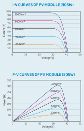
For this to work in any sort of reasonably efficient fashion, you need to match panel voltage to battery voltage pretty well. Looks like those panels output voltage somewhere around 34 volts, right? What is your battery voltage? Does the panel vendor supply a voltage/current chart in their spec sheet? Something like the one below?
By going with an Electrodacus if your battery is 24 volts, you could be cutting panel output by something like 30%. That would cut your fancy 450 watt panels down to 320 watts.
The problem gets much worse if you are going to run a 12v battery.

Choose new different panels or a different charge strategy would be my recommendation.

1689134441103.png
 
Back
Top