diy solar

diy solar

AC coupled battery supplying essential sub panel with Grid tied Micro inverter - Wiring question

mufasa

New Member
Joined
Apr 17, 2021
Messages
25
Hi, I have recently installed a 6.4kw enphase Micro inverter system, and is looking into install a subpanel and AC coupled battery solution to provide battery backup for things like fridge / network / some lighting / few plugs. However, besides putting these essential circuits in the sub panel, I likely will also include several more circuit that are not essential but power hungry ( Think 240v EV charger / Table saw / other woodworking tool ).

My goal for the battery is more for emergency battery backup than Time of use load shift. It would be nice to do load shift, but the primary reason is to handle brownouts ( Dame PG&E.. )

Currently I am not considering solutions like Ensemble / Powerwall mainly due to cost / performance. I hope to get this done with a smaller budget.

I saw the 48V DIY LiFe battery bank, seems to be a great solution for the battery side. Still reading more to find out which inverter are best for my need. ( hope to be able to supply at least 4-6kw, more kw would be great too. budget for inverter hope to be less than 3k ). Would apperciate suggestion for inverter and battery setup too.

But before getting to much into the inverter selection, my main question right now is the wiring.
I am still in the phase of trying to finalizing the wiring of the sub panel, and as I started to read about the inverter installation document, I find one popular way to install the inverter is to have it sit between the main panel and the essential panel. Generally it looks like this:

Main Panel ====== Battery inverter ====== Sub Panel with essential load ===== Solar AC breaker === combiner and array

However with the battery inverter in the circuit, the max current it can pass through become limited by the battery inverter. Currently I have only seriously read about the manual for Magnum MS4024, but seeing that it limits the current to 30A 240v makes me like this kind of setup less..

Also, what happens when you need to service the battery inverter for some reason? The essential panel and solar will need to be switch off too at that point.

I wonder how everyone solve this issue?

I am thinking of 2 possible way to get around this:
1. Add some kind of bypass transfer switch before the essential panel (maybe this? ), so we can manually choose power source of the essential panel to be main panel or the battery inverter, and get to uee higher current (in my case 60A) when directly connected to main panel.

2. Use multi-circuit transfer switch like this, so to the essential panel, the battery inverter is like a generator and never sits in between the two.

In both solution, the battery inverter still hooks up to the main panel for the upstream AC side to sense if the grid is up.

Which one of the above solution looks right? Or what will be a better way to solve this issue?
Nobody answered your question i see. I would alao like to see a reply to this, as I am finally ready to start on the AC side of my build.
 
Yup. I know there are many knowledgeable people on the forum that might have experience in this, maybe my question was not clear?

Anyway, I am still in the planning phase - sub panel is installed but not connected yet.
After reading a bit more, it seems like this kind of grid forming inverter might fit the bill to charge the battery when grid is down, and it should also does the frequency shift to tell the panel to stop charging when power is full.

I am now looking into setup a auto transfer switch between the main panel and sub panel - I wish the connection from main panel to sub panel is generally connecting directly, so it can make use of the full 60A. But I hope it to be auto transfer to using the battery pack and inverter when grid went down, and when the battery went down enough, the inverter should know to start the panel to charge it up again.

Somehow I can't find too much info regarding auto transfer switch.. Most of the ones I found is generac's transfer switch, option is not too much and it is generally exterior box ( my combiner and panel are in garage, hope to find flush mount transfer switch that is configurable enough to do what I want.

Or maybe someone who knows his stuff will tell me that it is better to pony up for powerwall? I don't know if what I am trying to do is safe / right / possible. I think it should be but don't know better yet..
 
Last edited:
I am in the same boat, same size Enphase system.
Wanting to add battery backup.
I don't think the Sigineer 15Kw inverter is a good fit, it needs there battery controller/ BMS to a contactor relay to cutoff the grid tied inverters
I think all all in one inverter is what we need, but I haven't found the right one that will handle 6.4K for a modest price.
Yup. I just bought a house with grid tied SMA sunny boys. Due to this awesome forum, I am building my own DIY batteries for 1/10th the price of buying ready made. Now I am in a quandry of what to do, as most grid tied solutions use high voltage batteries. My thought is to just scrap the grid tie system with a Hybrid DC system. I just bought a couple of LV6548 inverters, that can provide 13KW continuous, and I am building 26KW of batteries. I can just reuse the existing solar, and add a generator, and then I can tell the power company to take a hike!
 
If you go with a separate transfer switch, the ones I have seen will only connect to one source at a time, this would leave your battery with no source to charge between uses.

If you go with a different inverter, there are many rated with transfer switches rated to 60 amps.


If you are concerned about servicing the inverter, you can add a bypass breaker (and lockout) to directly power the sub panel when needed.

Something like a Outback Skybox might serve you well. It can frequency shift to control the micro inverters (when off grid/during an outage), has integrated 60a/48a transfer relays
 
Something like a Outback Skybox might serve you well. It can frequency shift to control the micro inverters (when off grid/during an outage), has integrated 60a/48a transfer relays
Thanks for the info!
I was reading their install manual.. https://www.solaris-shop.com/content/FX2012MT Installation.pdf
Seems like to get 60A output, you need a master and a slave box? So basically single skybox still only supports 30A?

If you go with a different inverter, there are many rated with transfer switches rated to 60 amps.
I must have not read enough.. Can you list some of the other option? Would love to see if there is one that would fit my setup


If you go with a separate transfer switch, the ones I have seen will only connect to one source at a time, this would leave your battery with no source to charge between uses.
I was planning to connect from Main panel to inverter + sub panel together , using the "Net Energy Metering, Utility Interactive with Backup – Example System Diagram" in this enphase document: https://enphase.com/sites/default/f...Considerations-AC-Coupling-Micros-Battery.pdf

Likely I will still add a ac cutoff before the inverter so I can service it without cutting the breaker to sub panel.

The wire I use between main and sub panel is a 2224 Al SER cable, should rated to 100A. On both main panel and sub panel input there will be a 60A breaker.. hopefully it won't trip often.
 
Ahh found this one would likely fit the bill too.

It does look like it need 2 stud space, need to think of where to put it..
 
Are you going to be getting permits or using UL listed components?
I have a permit from the city and as such am required to use a UL listed inverter.

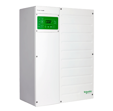
The options I looked into were Outback Skybox, Outback Radian, Schneider XW series, and Victron.
I'm sure there are others.

The Victron I didn't do as much research, so I'm less sure about the transfer rating. They are not split phase, so require either a second unit, or you could just use one 120v phase in the sub panel.

The linked manual is for an Outback FX. Check out the Skybox.

The Skybox is rated at 48 amps continuous.
The nec derating on a standard 60 amp breaker limits continuous current to 48 amps. So both the Skybox and Schneider had basically the same transfer rating.


I almost went with a Skybox. 2 months ago when I made the decision and purchased a Schneider XW pro. At that time, the Skybox was $4k
Now it's $2500?!?!

 
Ahh found this one would likely fit the bill too.

It does look like it need 2 stud space, need to think of where to put it..

It is exactly the size to bolt across a single 16" stud bay.

Double check your requirements. The XW is a great battery charger and inverter. Solid hardware with great capacity. But, when AC coupled it doesn't have the ability to automatically charge from solar output, or any way to track grid current and charge from excess output.

If you are just looking for back up or are DC coupled it's great. But, if you want to do any energy shifting and AC coupled it fails.
 
I have an Outback GS4048 with enphase micros (24: of them) and also AP Systems QS1 (3 of them)

I have a main panel and a sub panel already because of the size of the house.... So I turned the sub panel into a critical loads panel and left the feed from the main panel...I then back feed from a regular breaker to feed this panel from the inverter...I left in the main feed to the sub panel to be able to back feed the main during extended power down times from the sub panel and inverter... This also allows me to pull all the equiptment if I sell the house and sub panel won't need rewiring..

I think you will want to wire the micros into the sub panel so the inverter can frequency shift to control them during a power outage... I have half the micros in the sub panel and half in the main panel because just how over time I stepped through my build.

I don't think you want any large loads in the critical loads panel as to not risk someone turning them on and tripping off the breaker to the inverter.... Most times we don't even know the power is out till we hear our neighbors generator....

You can put in a bypass switch to feed the main or do like I did.
 
It is exactly the size to bolt across a single 16" stud bay.
Ahh. I saw the wrong graph, showing the additional power distribution panel.

Thanks for the insight about XW PRO. My requirement is backup first (!@#$ pg&e), but I would like to have option for energy shifting too. Will look into outback solution.


I have a main panel and a sub panel already because of the size of the house.... So I turned the sub panel into a critical loads panel and left the feed from the main panel...I then back feed from a regular breaker to feed this panel from the inverter...I left in the main feed to the sub panel to be able to back feed the main during extended power down times from the sub panel and inverter... This also allows me to pull all the equiptment if I sell the house and sub panel won't need rewiring..

So you mean your connection goes like this?

Code:
Main panel  ============ Sub panel ===  PV backfeed 2
    | ===  PV backfeed 1        | ===   GS4048 backfeed


And when grid goes down, the GS4048 battry supplies the whole house right? It does not need to sit between main panel and sub panel, and both of the PV can still start with GS4048 providing the 60Hz frequency?

If so yes I would love to do this! This is my assumption of how it would work before I started reading into all of these inverter's installation document. If this setup works for the timeshift and backup power feature I will totally be doing this..

I currently have 16 enphase micro. How is your experience with outback on a power outage? Is the switch from grid to battery near instantaneous? Does it trip the micros so it takes 5 min to start producing again?

I think you will want to wire the micros into the sub panel so the inverter can frequency shift to control them during a power outage... I have half the micros in the sub panel and half in the main panel because just how over time I stepped through my build.

I don't think you want any large loads in the critical loads panel as to not risk someone turning them on and tripping off the breaker to the inverter.... Most times we don't even know the power is out till we hear our neighbors generator....

You can put in a bypass switch to feed the main or do like I did.
As my yet to be connected critical load panel is in garage, the load I would like to put on it besides networking, basic light and 1 fridge 1 freezer, it will also includes future EV charger and another 240v plug for wood working tool. That is the main reason why I wish to keep the 60A capability. I am sure I won't be trying to cut wood when the grid is down, and hopefully there are something I can do to stop the future EV from trying to charge when grid is down.
 
I have 3 sub panels... One next to main panel and one in each of my garages...So the wiring goes: the inverter is fed from a garage sub panel, the inverter then feeds the critical loads panel that is next to the main panel....

The critical loads panel used to be fed from the main panel but now I keep that breaker off unless I want power the whole house off the inverter.... In that case I turn off the main house power feed and turn off the feed to the inverter and then turn the critical loads panel feed between the main panel and critical loads panel back on... This feeds power to the main and garage subs thus the whole house is fed of the inverter...

When I hooked up the inverter I made sure the phases feeding the inverter were the same as the wire between the critical loads and main panel....because if you forget to turn off the feed to the inverter when you back feed the main you are feeding the same power coming out of the inverter to the input of the inverter...I have done this a couple times without even realizing it till I went to put back to normal.... Not sure what would happen if you had those out of phase... This is the tricky part of my setup...
 
I really don't think you want an ev on the output side of the inverter.... They draw alot of power for a long time...

My 2 ev chargers have plugs on the feed so maybe have two outlets that you can choose which to plug it into....a plug on the main house side and a plug on the inverter side...

I have a level 2 charger and in four years we have lived in this house I have never needed to hook it up, or the want...I only charge at home with a 120 volt charger...I have plenty of time to charge over night.
 
The GS4048 or GS8048 have to have a firmware update to ac couple... But wasn't a big deal because most people install the latest firmware anyway.... The GS has tons of features like zero export it out of the unit, load assist, battery main use, time of day settings plus many more.... You can also buy the cheaper GS4048 and upgrade it to the GS8048 with an extra module...

I also use a 18 cell 280ah pack instead of 16 cell pack to get 2 kwh of extra capacity without having to buy a second pack. Surprised more people don't do this because many units will charge up into and able to use batteries in the 60 volt range...

The only negative is the GS is an older unit that have been around a long time but is also the cheapest.

Some on here have the newer Skybox but I don't know the advantage to that... Let me know if you find one... The Solark will do most of the same stuff but it's expensive....I didn't but the power distribution panel to keep the GS really cheap I just wired it directly through a small 3 double breaker panel and DC breaker.
 
Last edited:
I use a breaker-panel style transfer switch similar to the one you showed, but Squared-D QO. It came as a 30A generator switch with 100A feed-through, and I replaced both those breakers with 70A. Flip of a switch and my house is direct on grid rather than through the UPS.

The 15 kW Signeer for Tesla battery inverter you listed might be a problem, since Tesla never sold that battery. Or maybe there are alternative batteries.
It says 200W idle consumption, 50W standby. That's 4.8 kWh/day just to keep the nightlights on.

I use Sunny Island, which is 120V, 5750W continuous, 25W idle, 4W standby. Pass-through is 56A. Either two of them or a 120/240V transformer for split-phase.
If your Enphase do UL 1741SA frequency/watts then they might play nice. It would have been better to plan your battery solution when selecting the PV inverter system.

Table saw and the like - you'll want a high surge current. Signeer might do it. Sunny Island is 11kW surge per inverter. Many but not all of the high frequency inverters have anemic surge.

I use AGM batteries, which are great for high surge current and OK for up to a few hundred power outages in a decade.
DIY LiFePO4 should give 10x the cycle life and can be built for 40% the price of AGM. You need a BMS able to deliver your surge current. If in an area that freezes, address that.
 
Thanks for all the info and idea guys!

I understand that the idea of high surge circuit in essential load panel seems the biggest problem.
If I have more space on my 100A main panel I would pull another 240v circuit over to handle these surge. However that panel it is simply full now..
So either I have do some bigger rewire, or I would have to figure out how to make it fit in my setup here.

What if I place another small 4 or 6 space panel between the inverter and the main panel, put the surge load on that small panel, and then place the essential panel behind the inverter, maybe also with a pass through circuit from surge panel to essential panel, so I can service the inverter as needed?

Something like this:
Code:
Main panel ===== surge load panel === outback === essential panel === PV
                         |======== pass through ========|
                         |== EV charger
                         |== Table saw

Would this solve the problem?

In the case of backup power, the inverter should be able to handle the power requirement in the essential panel with room to spare now. When the sun is still out and PV is producing, maybe we can even push power back out to the main panel direction if I enable the passthrough? ( of course after cutting the mains switch in MBP )

And in time shift mode, the inverter will increase the output voltage so that load will pull from inverter first right?
Then if I use table saw during the time shift window, will the surge trip the breaker to the inverter?
Or will the surge consume the power from inverter, bring down the voltage from inverter and then I started pulling from the grid, along with the inverter? (combined output mode?)

Or is this just a pipe dream and I would dig a bigger hole for myself with this setup?
What are the glaring safety or code problem?
 
Last edited:
What if I place another small 4 or 6 space panel between the inverter and the main panel, put the surge load on that small panel, and then place the essential panel behind the inverter, maybe also with a pass through circuit from surge panel to essential panel, so I can service the inverter as needed?

While you're at it, a few more spaces. I put in a 12 slot, 24 circuit panel so I can install tandem breakers if needed.
Are you able to put tandem breakers in your main panel?

In the case of backup power, the inverter should be able to handle the power requirement in the essential panel with room to spare now. When the sun is still out and PV is producing, maybe we can even push power back out to the main panel direction if I enable the passthrough? ( of course after cutting the mains switch in MBP )

What are the glaring safety or code problem?

The glaring safety/code problem would be if you manually selected between grid and inverter.
For $50 I got a sheetmetal interlock. I put a backfed breaker next to the main; only one can be on at a time.
If the grid is down, I throw a few breakers (turn off main panel feed to UPS, turn off main breaker, turn on backfeed breaker) and inverter can feed any circuit. It is up to me not to use anything that draws too much.
 
While you're at it, a few more spaces. I put in a 12 slot, 24 circuit panel so I can install tandem breakers if needed.
Are you able to put tandem breakers in your main panel?
My essential is already a 12 space, 24 circuit panel. If the surge load panel is as big.. I don't know how I can explain why I share them on the same cable..

The glaring safety/code problem would be if you manually selected between grid and inverter.
For $50 I got a sheetmetal interlock. I put a backfed breaker next to the main; only one can be on at a time.
If the grid is down, I throw a few breakers (turn off main panel feed to UPS, turn off main breaker, turn on backfeed breaker) and inverter can feed any circuit. It is up to me not to use anything that draws too much.
You mean this interlock will be installed on main panel, not on the surge panel, to control the backfeed and main on main panel to be not on at the same time?

But I thought the code demands the backfeed panel for PV ( in this case, the breaker to sub panel chain ) should be a the opposite side of mains switch on main panel? If you mean the interlock should be on main panel, do you mean I should move the PV backfeed to be right by main switch on MBP?
( Not trying to fight about which code is right, just want to be sure I correctly understand what you are suggesting. )
 
Last edited:
Couple different panels and interlocks for different purposes.

I wanted to be able to bypass the UPS (battery inverter) if it failed, put the house straight to grid.
I did that with a "generator switch" which is two branch circuit breakers with an interlock.

The input from grid to my UPS (Sunny Island) that has PV inverter down stream is a breaker at the far end of the main panel. When on-grid, PV backfeeds through the UPS, into that breaker, through the length of the busbar, and out the main breaker. That's related to the 120% rule; main breaker could be 100% of busbar rating and PV breaker could be 20%, but at opposite ends so nowhere on busbar does current exceed 100%.
Note that is the input or "grid" connection of my Sunny Island. When grid fails, Sunny Island opens a relay and disconnects that.

If grid is down and I want to power something on the main panel (e.g. tools in the garage), that is when the output (protected loads) side of Sunny Island is back-fed into the main panel. To ensure inverter never fights with the grid, that is wired to a breaker in the main panel, adjacent to the main breaker and interlocked with it. Instead of feeding the main panel with a generator, I feed it with an inverter.

Both of my interlocked breakers gizmos are marketed as being for generator input.
 
Back
Top