diy solar

diy solar

AC coupled recommendation?

That's been the quest I have been on - to find a grit tie battery charge solution with the same zero-export intelligence that my GTIL inverters deliver for power generation - ie: to modulate charging power in order to maintain zero export.

Next you need to set priority between the two zero-export devices. You want battery charger to ramp up to max charging before GT inverters begin to ramp down production.

Ideally that would be set digitally. Alternatively, an analog offset in sensor reading.

If CT has a resistor so it outputs millivolts AC per amp, an offset of say "1A" reading could be accomplished using an AC transformer to generate say 12Vrms, feeding a resistor divider so one resistor develops 1 mVrms (assuming 1 mV per A CT). 12k ohm in series with 1 ohm.

If no resistor, just current, then AC current through an extra wire inside CT is one way to fake it.
Two, 120V to 12V transformers in series would produce 1.2V. 1.2 ohm 2W resistor would produce 1A

1A offset in "zero" point of 240V grid feed would be either 240W export or 240W import before other zero export device limits.
 
Next you need to set priority between the two zero-export devices. You want battery charger to ramp up to max charging before GT inverters begin to ramp down production.
That will be pretty easy. I will set the EVSE to charge from sunup to sundown. If there is no way to do that through it's app interface, my SCC has a dry contact that can be programmed for daylight (meaning minimum production level on the DC-coupled array). So in the worst-case, I need to run line to the EVSE through a relay controlled by the SCC.

This will assure the EV charger is only consuming excess energy while there is solar energy being produced.

The GTIL inverters are already being controlled through lamp timers, so I'll be able to turn them on at the beginning of peak (4pm) and run them until noon.

For the overlap period of 4pm until sundown, the GTILs will put out 0W whenever there is no power being imported (meaning there should be less than 6W being exported if the EVSE is operating properly) and whenever solar production is insufficient to offset load, the EVSE will be off (because there is no excess AC power for it to charge with) and the GTILs will kick-on to limit grid import to under 10 or 20W.

So from 4pm to ~7pm, I should export less than 18Wh and from ~7pm to 9pm I should import less than 40Wh.

The from 9pm to ~sunrise when the AC-coupled solar array kicks in, let's say ~7am and ~10 hours, the GTILs will limit import to less than ~200Wh (with the 120V AC charger automatically keeping the LiFePO4 battery topped up to ~20% SOC using the V2L power from the EV).
Ideally that would be set digitally. Alternatively, an analog offset in sensor reading.
I think my Epever's SCC dry contacts, controlled both by time (including 'sunrise' & 'sunset') as well as battery voltage will give me all the control I'll need. Switcing between offsetting export and offsetting grid consumption is easy because it is impossible to ever import and export from the grid at the same moment in time...
If CT has a resistor so it outputs millivolts AC per amp, an offset of say "1A" reading could be accomplished using an AC transformer to generate say 12Vrms, feeding a resistor divider so one resistor develops 1 mVrms (assuming 1 mV per A CT). 12k ohm in series with 1 ohm.

If no resistor, just current, then AC current through an extra wire inside CT is one way to fake it.
Two, 120V to 12V transformers in series would produce 1.2V. 1.2 ohm 2W resistor would produce 1A

1A offset in "zero" point of 240V grid feed would be either 240W export or 240W import before other zero export device limits.
I don't think I need to be concerned with any offset since both the EVSE as well as the GTILs already have offsets built in.

EVSE requires minimum grid export of 6W before it will kick-in to drop that grid export to 0-76W (assuming I elect to charge at 120VAC; 0-152W if I'm charging @ 240VAC).

As I've already stated, GTILs don't generate any output until consumption / grid import exceeds ~5-10W each (10-20W total).

I've got to understand more about the EVSE's minimum charging current 'steps' because if 0.6A / 76W or 152W is the minimum , an average export of 38W or 76W for ~9 hours in winter when solar energy is precious translates to 340 to 680Wh being exported meaning 255 to 510Wh wasted every clear day after being exported for 25% credit and then reimported to cover loads.

I'd be slightly better off having the EVSE charge at the next higher current and using the GTILs to provide the missing 36-76W (possibly using your CT sensor offset idea), but that seems complicated.

My current 1.14kW DC-coupled array generates a minimum of ~2500Wh (~2.2Wh/W) on clear days in the depths of winter, so just adding another 500W panel seems like an easier way to cover the energy lost to export.
 
I think you're missing some digits or something is odd in the math.

The J1772 (EVSE) standards dictate a minimum of 6.0 amps (not 0.6)
That is 720 or 1,440 watts minimum.
If you're array is 1.14 kw, you're going to need more panels to support charging a car.

I believe Hedges was talking about the decision to charge the car first or battery first. Which gets charged first?
For me it makes sense to charge the car first. But, with 1,440 watts as the base and steps of 240 watts, the home battery always gets some on a sunny day.

But, you've got DC coupled solar? I suppose that changes things. But, I'm stills unsure what you're going to do, so I can't offer much useful advice.
 
I think you're missing some digits or something is odd in the math.

The J1772 (EVSE) standards dictate a minimum of 6.0 amps (not 0.6)
That is 720 or 1,440 watts minimum.
Yes, the minimum is 6A, not 6W. Meaning a minimum of 720W @120VAC or 1440W @ 240VAC of available solar energy before it begins charging.

I just read the standard and it is 50% using 7 bits resolution (below 50% of max), so ~0.4% increments or 0.25A per bit.

So if charging at Level 1 (max of 12A @ 120V or 1.4kW), it is 5.5W per step below 0.7kW or 11W per step above 0.7kW, while charging at level 2 maxed to 16A @ 240V (3.8kW), it would be 15W per step below 1.9kW or 30W per step above 1.9kW.
If you're array is 1.14 kw, you're going to need more panels to support charging a car.
Sorry, I was not clear.

I’ve got a 4kW AC-coupled array capped at 3.5kW. That is the array that exports now and that I will need to capture in a battery rather than exporting I’m the future.

So no issue reaching the 6A minimun.

It’s not practical for me the expand that AC-coupled array but I have a second DC-coupled array used to charge my house battery (that powers my GTIL inverters).

I can easily add additional panels to that DC array and that is an easier way for me to compensate for AC-coupled energy list to export (because of the ‘steps’ in EVSE charge current) rather than looking for a complicated way to reduce that remaining unwanted export.
I believe Hedges was talking about the decision to charge the car first or battery first. Which gets charged first?
In my case, both get charged in parallel during the day.

DC array charges house battery.

AC array charges EV battery with excess energy after powering loads.

Overnight, the EV’s V2L port recharges the house battery like a generator when needed as the GTIL inverters offset home consumption.

For me it makes sense to charge the car first. But, with 1,440 watts as the base and steps of 240 watts, the home battery always gets some on a sunny day.

But, you've got DC coupled solar? I suppose that changes things. But, I'm stills unsure what you're going to do,so I can't offer much useful advice.

Today, I use AC array to power loads and export any excess during the day.

The house battery is charged from a second DC array which offsets loads as long as battery energy remains after the sun sets.

I’m really happy with the way it works but after I get bumped to the successor tariff and export gets credited at ~25% retail rather than the full retail credit we get today, I need to find a way to capture as much AC energy as possible to avoid export.

So charging a V2L-capable EV with excess AC-coupled solar energy using an EVSE charger configured to consume most of the energy that otherwise would be getting exported sounds like the easiest long-term solution.

Instead of getting exported to grid, most of the excess AC generation gets stored in the EV’s battery (we’re talking about ~8.5kWh per day in December, so no big deal).

Then, as the GTIL inverters drain the DC energy that had been stored in the house battery from the DC array, a ‘generator’ relay can be used to turn on a 10A / 320W battery charger powered by the EV’s V2L port to keep the house battery topped off above empty and powering the GTILs (draining that ~8.5kW that had been stored).

The only thing I don’t like with this solution is the poor efficiency - I figure I’ll only get ~660Wh of usable AC power to offset consumption through this multi-hop path for every 1000Wh of AC energy I put into the EVSE rather than export it.

But 66% is waaay better than the 25% my utility is offering ;).

If there was a way to output grid-tie power from the EV (V2G?), that would allow me to improve efficiency to ~81% but that requires a grid-tie inverter in the EV to sync to the grid signal as well as some control mechanism to limit the output power to the level needed to offset loads (as my GTIL inverters do today).

A bidirectional EVSE-like EV charger that can tell the EV when to consume enough power to minimize export while also being able to tell the EV when to export enough power to offset consumption and minimize import would be a dream, so hopefully something like that is in the works and will be available for me when the time comes…
 
Last edited:
I believe Hedges was talking about the decision to charge the car first or battery first. Which gets charged first?

What I meant was, if you have a zero export system that absolutely, positively, never exports a single watt ...
And you have a car charger controlled to zero exported watts by putting them in car battery ...

Your GT PV inverter may get output curtailed to avoid exporting, without ever charging battery.

Now if fafrd has 3.5 kW system with NEM export approval, plus
additional PV configured to supply power to the house (and even the grid?) but never push export above 3.5 kW, then
there is plenty of export power to enable the car charger.
The 3.5kW is the offset in that case.

If power generation is limited to zero export +/- measurement error and dump load to EV battery is also set at zero grid power +/- measurement error, I was looking for ways to offset them a bit, so 100% of available PV gets produced as long as EV battery can absorb it.
Yeah, I’m not planning on throttling the Microinverters or trying to limit export to 0Wh (or use my AC-coupled array for backup power during an outage).

Seems easier to generate as much AC power off of the AC-coupled array as possible and use the EVSE charger to minimize the amount being exported.

You’ll lose 75% of the value of what you export versus losing ~34% of the value of what you charge into the EV for later use powering loads (so not exporting is 264% the efficiency of exporting), but my 2016-vintage Microinverters have no frequency-shift curtailment feature meaning it’s just ON of OFF control for a hybrid inverter.

So I’ll just accept some export and live with it. Just being able to bound export level to ~1% of peak AC-coupled power generation solves the lion’s share of the issue.

I’m still not exactly understanding how finely the OpenEVSE can control / staircase charge power.

They seem to have 40A and 48A models, while the standard may hardlimit a 240V charger to operate at a limit of 80A (even if that charge current cannot be supported),

So worst-case, if I have a 40A 240V model that charges with a theoretical maximum of 80A / 19.68kW, I’d always be charging using excess solar power at well under 50% or 9.84kW , translating to steps of at most 77W, meaning about 2.2% of my maximum AC generation of 3.5kW or an average of about 1.1%.
 
I’m still not exactly understanding how finely the OpenEVSE can control / staircase charge power.
I may be a question of how finely the on-board charger in the vehicle can modulate. I don't remember the details but when I was manually changing my Clipper Creek I noticed there was a difference between my cars. This was during a period before I had a PTO and I was trying to use as much power as my system was producing. I don't remember the details but there was a difference in the steps between a Fiat 500e and a Tesla MX. My memory is vague but one of the cars could only increment up or down in 6 Ampere steps. Eventually I gave up on that experiment and went in a different direction.
 
Last edited:
I’m still not exactly understanding how finely the OpenEVSE can control / staircase charge power.

The steps are 1 amp, 6+ amps in one amp steps.

The difference between the 40a and 48a kit is a heavier gauge cable.

Many EVs max out AC (level 2) charging at 32 amps or less. That's 7,620 watts, lots more solar than I've got.
 
The steps are 1 amp, 6+ amps in one amp steps.

The difference between the 40a and 48a kit is a heavier gauge cable.

Many EVs max out AC (level 2) charging at 32 amps or less. That's 7,620 watts, lots more solar than I've got.
I’ve been reading up on the J1772 standard here: https://en.m.wikipedia.org/wiki/SAE_J1772

It appears to be hard-coded for a range of 6 to 80A, so 6A is the minimum charge current that can be supplied in any implementarion.

The standard then allows the duty-cycle to increase of 10us ‘steps, each 10us / 1% increase in duty cycle ‘step’ to correspond to an increase of 0.6A in charge current up to a maximum of 51A at a duty cycle of 85% (850us out of 1000us).

So the standard itself will support increments of as little as 0.6A / 144W but that requires the EV charger itself to accept such small increments and also requires the EVSE charger to implement steps that are that fine-grained.

I’ve only got a maximum of 14.6A @ 240V (3.5kW) of solar power to charge from, so I’ll never use more than 36.5% of the maximum charge power available from a 40A OpenEVSE charger, but I’d prefer a charger and an EV that can charge in 0.6A / 144W increments above 1.44kW since this would allow me to minimize the unused AC energy that gets exported to an average of ~72W rather than the average of ~144W I’s get with 1.2A / 288W increments.

For us ‘needing to avoid export’ types, the optimal (long-term) solution would be a hybrid inverter with both AC-coupled and DC-coupled solar power that can communicate using a protocol such as RS485 with an EVSE charger to tell it what target, minimum, and maximum charge current it would like it to use.

When using a charge current / power that exceeds available excess solar power, the hybrid inverter can supply the missing power using DC-coupled solar power (or even the house battery if needed) so there is never any import (above some minimum threshold).

And when using a charge current / power that is below available excess solar power, the hybrid inverter can consume the remaining excess AC solar power to charge the house battery to avoid export.

So during daylight hours it should be possible to maintain zero-import and zero-export as long as neither house battery or EV battery have charged up to full.

And at night, the V2L port on an EV can be used to keep the house battery charged with a 120VAC charger to a minimum ‘near-empty’ level at a cost of ~19% loss of efficiency / energy.

Or if there is a new standard that emerges for grid-tied power from an EV (V2G?), the hybrid inverter could call on the EV to power house loads directly after the house battery is drained, avoiding that 19% loss of efficiency / energy.

I’ve got 2 years to go before I’ll have an EV and 10 years to go before I’ll need to avoid export, so hopefully the technology continues to mature over that timeframe…
 
For us ‘needing to avoid export’ types, the optimal (long-term) solution would be a hybrid inverter with both AC-coupled and DC-coupled solar power that can communicate using a protocol such as RS485 with an EVSE charger to tell it what target, minimum, and maximum charge current it would like it to use.
I have a hybrid inveter with both AC and DC couple solar but the challenge for me will be something like the RS485 communication. If I knew anything about an Arduino or similar device I would put a CT on the output of the hybrid and have the CT reading send a duty cycle from the Arduino so that the EV charger drew enough Amps to consume the power produced by the solar. As is is on sunny days I just set the Amperage draw of the car to pull enough current to match my solar output.
 
I have a hybrid inveter with both AC and DC couple solar but the challenge for me will be something like the RS485 communication. If I knew anything about an Arduino or similar device I would put a CT on the output of the hybrid and have the CT reading send a duty cycle from the Arduino so that the EV charger drew enough Amps to consume the power produced by the solar. As is is on sunny days I just set the Amperage draw of the car to pull enough current to match my solar output.
Getting into building your own controller and programming your own protocols offers an alternative pathway, but what a pain.

I’ve got enough time that I’m hopeful new standards and implementations will emerge…

California deciding to essentially end NEM going forward should motivate a lot of innovation and an all-in-one hybrid including both EV charging as well as house battery charging is such an obvious solution to capitalize on fully-amortized AC-coupled solar systems being forced off of NEM that I believe it’s only a question of when and not if.

There is a great deal that could be achieved with a multi-CT-based smart meter serving as the brain of the whole system and communicating with both battery inverter as well as EVSE charger (along with newer-generation Microinverters and String Inverters)…
 
There is a great deal that could be achieved with a multi-CT-based smart meter serving as the brain of the whole system and communicating with both battery inverter as well as EVSE charger (along with newer-generation Microinverters and String Inverters)…

I linked to my build thread earlier.
I've got it set up with a raspberry pi and current sensors controlling charging the ESS (battery inverter) and EVSE.
All the heavy lifting was done and is open source. I purchased the board and current sensors from the dev.

It's not an off the shelf solution (I don't think one exists without spending $$$$$)

I think I've got a whopping 20-30 lines of code into getting it working properly. (Most of that is math to figure out the charging wattage for each device, that's the easy part)
This was my first project involving real coding, I think I did the"Hello World" type stuff a decade ago.
My hat’s off to you, I’m impressed!

What battery inverter do you have that supports variable / controllable charge-current and is there a standard for the communication protocol to control it?

And same question for the EVSE - what model do you own and is it an open standard you use for the protocol to control it using your Raspberry Pie?

It sounds like you’ve put together the central ‘brain’ I’ve been thinking about -was it a kit and if so, can you share a link?

Was your system permitted and inspected and if so, did you get it passed in some basic configuration before adding this intelligence post-inspection?
 
My hat’s off to you, I’m impressed!
Thanks! I'm pretty happy with how it all came together. But, it coincided with increased driving (and more charging)
So, now I'm thinking about adding some DC coupled solar to charge the ESS.

Most of the answers are in the thread.
I haven't updated in a while, because the EVSE is in progress now, but I'm working on it.


What battery inverter do you have that supports variable / controllable charge-current and is there a standard for the communication protocol to control it?
Schneider XW6848 pro

Edit: they publish the communication protocol. It's modbus. Sounds more intimidating than it is.

And same question for the EVSE - what model do you own and is it an open standard you use for the protocol to control it using your Raspberry Pie?
I linked to it earlier, we've been discussing it.
Control is done via an MQTT message from the pi. I'm pretty sure the "open" in OpenEVSE is for open source.

It sounds like you’ve put together the central ‘brain’ I’ve been thinking about -was it a kit and if so, can you share a link?
Linked already in this thread and in my build thread.

Was your system permitted and inspected and if so, did you get it passed in some basic configuration before adding this intelligence post-inspection?
Yes to both.
The solar is grid tied, permitted, and self installed in 2018
The update/upgrade was permitted with only the Schneider XW and the required gateway.
I added the current sensors, pi, and EVSE later.

Ugh, another edit:
I should clarify. The PV was installed Dec 2018. The ESS was installed spring 2021
 
Thanks! I'm pretty happy with how it all came together. But, it coincided with increased driving (and more charging)
So, now I'm thinking about adding some DC coupled solar to charge the ESS.

Most of the answers are in the thread.
I haven't updated in a while, because the EVSE is in progress now, but I'm working on it.


Schneider XW6848 pro

Edit: they publish the communication protocol. It's modbus. Sounds more intimidating than it is.


I linked to it earlier, we've been discussing it.
Control is done via an MQTT message from the pi. I'm pretty sure the "open" in OpenEVSE is for open source.


Linked already in this thread and in my build thread.


Yes to both.
The solar is grid tied, permitted, and self installed in 2018
The update/upgrade was permitted with only the Schneider XW and the required gateway.
I added the current sensors, pi, and EVSE later.

Ugh, another edit:
I should clarify. The PV was installed Dec 2018. The ESS was installed spring 2021
Cool. I’ll read through your thread.

So when you got the XW permitted and installed this year, was there no battery or which battery? When I was considering an XW, one of the things that turned me off is that it seemed to only work with certain batteries…

Then you came back post inspection to install the ‘brain’ and everything is working the way you’d hoped - sounds as though this capability is much closer-at-hand than I’d thought…
 
The XW is a battery inverter/charger only (it has internal transfer switches too, but only converts to/from the battery)
It's was permitted and installed with repurposed EV batteries.

The XW doesn't care what type of battery. The charge/discharge parameters are very adjustable.
If you want communication with the BMS, those options are limited.
I've got a Batrium BMS and I believe it will communicate, I've seen a little proof of successful communication, but I need to spend some time verifying it works properly. It's not high on the priority list.
 
Cool. I’ll read through your thread.

So when you got the XW permitted and installed this year, was there no battery or which battery? When I was considering an XW, one of the things that turned me off is that it seemed to only work with certain batteries…

Then you came back post inspection to install the ‘brain’ and everything is working the way you’d hoped - sounds as though this capability is much closer-at-hand than I’d thought…
Read through your thread - nice build!

That thread is fantastic but it’s a bit difficult to get a bead on the components you used in the final system once it was complete.

There is not much in their about how you are controlling your EV charging and I, for one, would be very interested in a block diagram of your final system and a description of how the control works to deliver the performance you’ve achieved.

I thought this was a fantastic post: https://diysolarforum.com/threads/adding-schneider-xw-pro.19090/page-8#post-301234

Explaining how you’ve achieved zero export and zero import using your RasberryPie-based energy monitor / brain to control EV charger and hybrid inverter would make a very interesting thread…

I’d pretty much given up on Schneider but your system represents exactly what I’m aiming for, so the Conext is now my reference until something better has been proven.

By the way, do you know if the Conext SW could deliver similar functionality to what you achieved with the XW (at lower performance ratings, obviously)?
 
Thanks,
I need to ask around and see what program others are using to draw block diagrams. Using ms paint seems painful...

I don't have enough battery or PV to hit zero import/export, but I'm happy to add some more details. The set up I've got should get there, just set some different parameters.

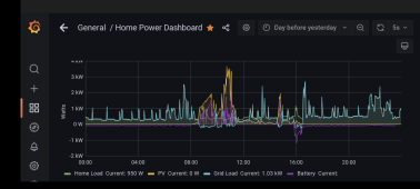
I am just this week installing the current sensor to monitor the EVSE, so it doesn't show on the graph quite yet. Also, it's been overcast. Makes the graphs looks like a hot mess.
Once, I've got the last current sensor installed and a sunny day I'll get a good graph.

Screenshot_20211227-184843.png

The SW line is a related but different, I'm not fluent in the differences.

I know the SW can't do any export if that matters to you. Meaning it could not power loads "upstream" or on the main panel.
The internal transfer relays are rated at 30 amps.

Schneider published their modbus protocol, it would be a quick check to verify the same commands are available. Knowing how things go, I'd expect both use the same exact commands.
 
Thanks,
I need to ask around and see what program others are using to draw block diagrams. Using ms paint seems painful...

I don't have enough battery or PV to hit zero import/export, but I'm happy to add some more details. The set up I've got should get there, just set some different parameters.

I am just this week installing the current sensor to monitor the EVSE, so it doesn't show on the graph quite yet. Also, it's been overcast. Makes the graphs looks like a hot mess.
Once, I've got the last current sensor installed and a sunny day I'll get a good graph.

View attachment 77329

The SW line is a related but different, I'm not fluent in the differences.

I know the SW can't do any export if that matters to you. Meaning it could not power loads "upstream" or on the main panel.
The internal transfer relays are rated at 30 amps.

Schneider published their modbus protocol, it would be a quick check to verify the same commands are available. Knowing how things go, I'd expect both use the same exact commands.
If the SW cannot offset grid-side load, that’s all I need to hear -it’s XT for me.

As far as the EVSE current sensor, I thought you were controlling the EV charging power from your Raspberry Pie monitor / brain?

No rush, but I’m very interested to understand how you’ve gotten your system working and who is doing what where…
 
Back
Top