Sure there is no rush since it's weekend. Nami hasn't read my last message yet.I must run, will get back to you later


You are using an out of date browser. It may not display this or other websites correctly.
You should upgrade or use an alternative browser.
You should upgrade or use an alternative browser.
Active balancer, make it smart!?
- Thread starter Vi s
- Start date
Hi HansMax,
From my experience an end of charge voltage of 13.9... 14.0 V is a good compromise. 3.5 V max cell voltage keeps the stress low, gives you 100% SOC after the current has tapered off, guarantees ample margin to the 3.65 V max cell voltage and a 3.7 V overvoltage disconnect.
13.9 V to 14.0 V is too low for the normal passive balancer. But this drawback is compensated by the usage of "our smart active balancer" .
I am glad you brought up and continue to pursue this important issue.
Cheers Hans
When I read that even at 3.45V one could slightly overcharge ones battery with a slow charge speed i thought maybe i should lower my charge end voltage from 13.8V to 13.7V or even lower... During most day hours of the day the charge power is only 2-25w and about 2 hours up to 96W (320wh yield at most per day, 680wh battery. My battery cycles usually between 70 and 100%soc. Hardly ever goes above 13.41V even at 100%soc. Maybe they sold me higher capacity cells than they stated ? but often I feel my cells are bottomless. They stay quite a long time at 100% (coloumb counter) before the voltage goes above 13.41V (at a slow slow charge speed). Voltage is really no good indicator for lifepo4-SOC under certain circumstances.
I thought so too. I am truly wondering because i checked the coloumb counter and it seems to be precise. I will have to check it again. It even counts below 1w loads or charges unlike the BMS coloumb counter.Voltage is a good indicator, 2.5V is 0% and 3.65V is 100%. Everything else is a bit of guesswork. ? I would say at 13.41V you are not 100%.
SOC or coulomb counter are only precise when reset. This can only occur at 0% or 100% and in between they will drift. Tesla telks owners using LFP batteries to charge to 100% once a week to reset range/SOC. Why do we expect our batteries to work differently? LFP is safe and great for our purposes but you can't operate 20-80%, voltage curve is to flat. Cycle to near 100% and you will have no problems.
Hans Kroeger
New Member
- Joined
- Dec 30, 2020
- Messages
- 131
Max,Hi Hans
Sure i can. Could you explain to me why you think monitoring total voltage would be significantly more advantageous or better than just the B1 voltage? I mean i should also give them a good reason why they should go through the trouble to change the design.
With single cell monitoring the risk is much higher that the balancer is not turned on at the end of charging with a low voltage.
Example: charging with 13.9 V, cells 1 to 4 may be at 3.35 + 3.50 + 3.50 + 3.55 V. The balancer will stay off.
You can play around with theses numbers but you will end up with the same result.
Arguing from a different point of view: when charging wth 13.9 Volts it is safe to turn on the balancer if the total battery voltage goes above 13.5 Volt (or 13.6 V) no matter what the individual cell voltages are. Turning the balancer off at 13.4 V (or 13.3 V) leaves ample margin for the balancer to do its job.
The change of the circuit should be easy. The monitoring input of the comparator would have to be disconnected from the +B1 terminal and be connected to the +B4 terminal. The actual comparator may have to be exchanged against another type which can accept 16 V or more.
Summary: the actual design of the active balancer invites you to charge at voltages far below the normal 3.6 V +/- cell voltage, required by normal passive balancers.
Low end of charge voltages like 13.9 V total increase the life expectancy of the cells.
Unfortunately with a low charging voltage, single cell monitoring for on/off control of the balancer is not reliable to turn on the balancer when needed.
Battery voltage monitoring however will resolve this shortcoming.
Hope that is reason enough for Hankzor to think about su h an improved design.
Regards Hans
Hans Kroeger
New Member
- Joined
- Dec 30, 2020
- Messages
- 131
Horsefly
Solar Wizard
Where is this from?I guess, many of the above questions and comments will be answered by the following chart:
Many thanks for this chart!I guess, many of the above questions and comments will be answered by the following chart:
If i read this chart correctly then even at 0.04C i could charge it till 3.65V without overcharging it. Since i stay below 3.65V my cells should be fine.
Also another takeaway is (if i understood correctly) if i would charge CC with say 0.01C i could overcharge the cells given i do this long enough. If i would charge CC till 3.45V with 0.5C and then switch to CV and stop at 0.1C i could never overcharge them but would come close to if not hit 100%soc.
Got your point, will convey your suggestion and reasons to her.Max,
With single cell monitoring the risk is much higher that the balancer is not turned on at the end of charging with a low voltage.
Example: charging with 13.9 V, cells 1 to 4 may be at 3.35 + 3.50 + 3.50 + 3.55 V. The balancer will stay off.
You can play around with theses numbers but you will end up with the same result.
Arguing from a different point of view: when charging wth 13.9 Volts it is safe to turn on the balancer if the total battery voltage goes above 13.5 Volt (or 13.6 V) no matter what the individual cell voltages are. Turning the balancer off at 13.4 V (or 13.3 V) leaves ample margin for the balancer to do its job.
The change of the circuit should be easy. The monitoring input of the comparator would have to be disconnected from the +B1 terminal and be connected to the +B4 terminal. The actual comparator may have to be exchanged against another type which can accept 16 V or more.
Summary: the actual design of the active balancer invites you to charge at voltages far below the normal 3.6 V +/- cell voltage, required by normal passive balancers.
Low end of charge voltages like 13.9 V total increase the life expectancy of the cells.
Unfortunately with a low charging voltage, single cell monitoring for on/off control of the balancer is not reliable to turn on the balancer when needed.
Battery voltage monitoring however will resolve this shortcoming.
Hope that is reason enough for Hankzor to think about su h an improved design.
Regards Hans
Regards Max
Hans Kroeger
New Member
- Joined
- Dec 30, 2020
- Messages
- 131
Correct, if you turn off the charger at 3,65 V AND at 0.04C Amps.Many thanks for this chart!
If i read this chart correctly then even at 0.04C i could charge it till 3.65V without overcharging it. Since i stay below 3.65V my cells should be fine.
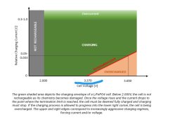
I am not clear about that statement. The important information of that curve is the red line:Also another takeaway is (if i understood correctly) if i would charge CC with say 0.01C i could overcharge the cells given i do this long enough. If i would charge CC till 3.45V with 0.5C and then switch to CV and stop at 0.1C i could never overcharge them but would come close to if not hit 100%soc.
If you charge with CC up to the point where the charger goes to CV, the red line tells you for that particular voltage at which current level you must turn off the charger, in order not to overcharge the cell.
e.g.: If you charge a 100 Ah cell with 0.2 C (=20 A) in CC mode up to CV = 3.65 V then you must wait in CV mode at 3.65 V until the current tapers off to 0.033 ...0.05 C (3.3 ...5 A for a 100 Ah cell). Then you must stop charging (or reduce the Voltage to 3.37 V maximum) in order not to overcharge the cell.
Note: All chargers with a floating voltage of more than 3.37 V per cell will cause a reduced life time .....
Let's say i charge with 0.5C. according to that chart i can charge even above 3.65V and i am still not overcharging the cell (still in the green). Can this be right? What is the voltage at 0.5C at which the cell is overcharged? Overcharging means charging a cell beyond its designed capacity right!? So why does the voltage (pressure) rise? Since voltage and capacity are not linear it can't be only because the cell gets closer and closer to full capacity or?Correct, if you turn off the charger at 3,65 V AND at 0.04C Amps.
I am not clear about that statement. The important information of that curve is the red line:
If you charge with CC up to the point where the charger goes to CV, the red line tells you for that particular voltage at which current level you must turn off the charger, in order not to overcharge the cell.
e.g.: If you charge a 100 Ah cell with 0.2 C (=20 A) in CC mode up to CV = 3.65 V then you must wait in CV mode at 3.65 V until the current tapers off to 0.033 ...0.05 C (3.3 ...5 A for a 100 Ah cell). Then you must stop charging (or reduce the Voltage to 3.37 V maximum) in order not to overcharge the cell.
Note: All chargers with a floating voltage of more than 3.37 V per cell will cause a reduced life time .....
Hans Kroeger
New Member
- Joined
- Dec 30, 2020
- Messages
- 131
Sorry, I don't remember. But you find similar presentations in scientific papers dealing with that subject.Where is this from?
Horsefly
Solar Wizard
When you didn't answer I used Google to find it. It was the (somewhat) famous Nordkyn Design site. I think that is a good site, and the author does know lots of stuff, but he does say some stuff that doesn't seem consistent with most other experts. As an example, he says LiFePO4 batteries are subject to "memory effects" which can be detrimental to he lifetime of the battery. Most places you find will say either LiFePO4 does not have any memory effect, or that it is insignificant (or that it has an insignificant impact).Sorry, I don't remember. But you find similar presentations in scientific papers dealing with that subject.
Hans Kroeger
New Member
- Joined
- Dec 30, 2020
- Messages
- 131
Let's say i charge with 0.5C. according to that chart i can charge even above 3.65V and i am still not overcharging the cell (still in the green). Can this be right?
No, there is much more to consider when charging LFP cells. Cell chemistry requires to stay within a certain envelope with your charging parameters (current, voltage, temperature) in order not to put your cell under stress. Therefore the manufacturer of the cell defines certain limits to be taken into account. Technically you may charge your cell with 0.5 C up to 3.7 Volts without overcharging it. But this will reduce the lifetime of your cells below what the manufacturer has specified for the maximum allowed cell voltage of 3.65 V.
It is important to understand how Amps and Volts play together during charging with the CC / CV charger. When you turn on a charger, it starts in its CC mode. It pushes a certain amount of Amps into the battery and keeps this current constant. It is only the battery which defines the actual voltage based on the growing charge it stores. The battery voltage starts to increase. The charger stays in CC mode until the battery voltage reaches the preprogrammed end of charge voltage of the charger. Once the end of charge voltage is reached, the charger switches from its CC mode to its CV mode. Now the charger keeps the voltage constant. Now it is the battery which defines the actual current based on the growing charge it stores.What is the voltage at 0.5C at which the cell is overcharged? Overcharging means charging a cell beyond its designed capacity right!? So why does the voltage (pressure) rise? Since voltage and capacity are not linear it can't be only because the cell gets closer and closer to full capacity or?
Finally, the concerned curve above tells you at which point in time the battery is 100 % charged, and at which current the charger must be turned off in order not to overcharge the battery. Without such a curve you wouldn't know when to stop charging. There is nothing to tell you when your battery is full. Reaching 3.65 V is no indication of a 100% SOC.
Neither is 2.5 Volts an indication for an empty battery, as someone stated above. In many cases it does not help to oversimplify matters because it cam lead to wrong conclusions.
Battery chemistry is not a mystery but it is very complicated.
Hans Kroeger
New Member
- Joined
- Dec 30, 2020
- Messages
- 131
He is correct, LFP cells have a memory effect. But this is quite different from what we know about batteries which must be discharged in order to accept another full charge. As you say, the impact is insignificant.When you didn't answer I used Google to find it. It was the (somewhat) famous Nordkyn Design site. I think that is a good site, and the author does know lots of stuff, but he does say some stuff that doesn't seem consistent with most other experts. As an example, he says LiFePO4 batteries are subject to "memory effects" which can be detrimental to he lifetime of the battery. Most places you find will say either LiFePO4 does not have any memory effect, or that it is insignificant (or that it has an insignificant impact).
Horsefly
Solar Wizard
Actually, if you read the Nordkyn article he spends time talking about this maximum termination current, but he admits that if you terminate at any of the shown voltages at 0.05C the only impact is that the cell will not be at 100% SoC, and he then admits that most people believe not getting to 100% SoC is a good thing anyway.No, there is much more to consider when charging LFP cells. Cell chemistry requires to stay within a certain envelope with your charging parameters (current, voltage, temperature) in order not to put your cell under stress. Therefore the manufacturer of the cell defines certain limits to be taken into account. Technically you may charge your cell with 0.5 C up to 3.7 Volts without overcharging it. But this will reduce the lifetime of your cells below what the manufacturer has specified for the maximum allowed cell voltage of 3.65 V.
It is important to understand how Amps and Volts play together during charging with the CC / CV charger. When you turn on a charger, it starts in its CC mode. It pushes a certain amount of Amps into the battery and keeps this current constant. It is only the battery which defines the actual voltage based on the growing charge it stores. The battery voltage starts to increase. The charger stays in CC mode until the battery voltage reaches the preprogrammed end of charge voltage of the charger. Once the end of charge voltage is reached, the charger switches from its CC mode to its CV mode. Now the charger keeps the voltage constant. Now it is the battery which defines the actual current based on the growing charge it stores.
Finally, the concerned curve above tells you at which point in time the battery is 100 % charged, and at which current the charger must be turned off in order not to overcharge the battery. Without such a curve you wouldn't know when to stop charging. There is nothing to tell you when your battery is full. Reaching 3.65 V is no indication of a 100% SOC.
Neither is 2.5 Volts an indication for an empty battery, as someone stated above. In many cases it does not help to oversimplify matters because it cam lead to wrong conclusions.
Battery chemistry is not a mystery but it is very complicated.
Terminating the charge at a higher residual current simply equates to stopping the charge short of 100% SOC; this is commonly done as well as it is perceived to be easier on the cells, but the effective difference only amount to a few minutes of charging in most cases and a tiny fraction of capacity only. Lithium batteries just charge too easily.
To me that part of his article is a bit of a waste.
Many thanks Hans for taking your time to explain it to a novice like me, learning a lot!No, there is much more to consider when charging LFP cells. Cell chemistry requires to stay within a certain envelope with your charging parameters (current, voltage, temperature) in order not to put your cell under stress. Therefore the manufacturer of the cell defines certain limits to be taken into account. Technically you may charge your cell with 0.5 C up to 3.7 Volts without overcharging it. But this will reduce the lifetime of your cells below what the manufacturer has specified for the maximum allowed cell voltage of 3.65 V.
It is important to understand how Amps and Volts play together during charging with the CC / CV charger. When you turn on a charger, it starts in its CC mode. It pushes a certain amount of Amps into the battery and keeps this current constant. It is only the battery which defines the actual voltage based on the growing charge it stores. The battery voltage starts to increase. The charger stays in CC mode until the battery voltage reaches the preprogrammed end of charge voltage of the charger. Once the end of charge voltage is reached, the charger switches from its CC mode to its CV mode. Now the charger keeps the voltage constant. Now it is the battery which defines the actual current based on the growing charge it stores.
Finally, the concerned curve above tells you at which point in time the battery is 100 % charged, and at which current the charger must be turned off in order not to overcharge the battery. Without such a curve you wouldn't know when to stop charging. There is nothing to tell you when your battery is full. Reaching 3.65 V is no indication of a 100% SOC.
Neither is 2.5 Volts an indication for an empty battery, as someone stated above. In many cases it does not help to oversimplify matters because it cam lead to wrong conclusions.
Battery chemistry is not a mystery but it is very complicated.
Really trying to wrap my head around this complicated chemistry, like why does voltage rise so steep in the beginning and end and why is it so flat in the middle at CC?? Certainly there are other factors than current and temperature at play i don't know of yet. Maybe i find one day an understandable comparison or model how this all works. With the common comparison/model to water pressure (voltage) and volume (current) i can't really make sense to it yet. Anyhow interesting subject!
All batteries are complicated chemistries and they have different voltages and operating curves. LiFePo4 just happens to have a very flat curve which most are not used to. Great, as the voltage is stable across most of the capacity but also makes it difficult to know what the actual capacity is. The head and tail of the curves are very distinctive so this is where you need to be to accurately assess state of charge.
Many thanks for sharing the source of this chart!Actually, if you read the Nordkyn article he spends time talking about this maximum termination current, but he admits that if you terminate at any of the shown voltages at 0.05C the only impact is that the cell will not be at 100% SoC, and he then admits that most people believe not getting to 100% SoC is a good thing anyway.
To me that part of his article is a bit of a waste.
Very interesting information + nicely written in an easy to follow manner!
Hans Kroeger
New Member
- Joined
- Dec 30, 2020
- Messages
- 131
Max,Many thanks Hans for taking your time to explain it to a novice like me, learning a lot!
Really trying to wrap my head around this complicated chemistry, like why does voltage rise so steep in the beginning and end and why is it so flat in the middle at CC?? Certainly there are other factors than current and temperature at play i don't know of yet. Maybe i find one day an understandable comparison or model how this all works. With the common comparison/model to water pressure (voltage) and volume (current) i can't really make sense to it yet. Anyhow interesting subject!
I know, it is difficult to understand how the battery behaves (voltage, current, charge) when being connected to a CC/CV charger. In particularr one must understand that such a charger operates with two controlloops, one to keep the output current constant and one to keep the output voltage constant. When in CC mode the controller reads the actual current and compares it with its reference value. In case the current tends to go below the reference, the charger increases the output power a bit in order to keep the current constant.
The current transports charge (coulomb) into the battery which stores this charge. The amount of charge being stored in the battery will grow. As a consequence the battery voltage will grow too, very slow in the flat part of its charge curve, and faster towards the end of this curve. The growing battery voltage is recognized by the CC control loop which reacts by increasing the output power to keep the current constant.
As soon as the charger detects that the battery voltage reaches the preprogrammed "end of charge voltage" (absorption voltage) it turns off the CC mode and switches over to the CV mode. From here on, the controller will keep the voltage constant. The battery is nearly full and reduces the current being drawn from the charger. If the CV control loop detects a tendency of the voltage to go up, it will reduce its output power in order to keep the voltage constant. Thus the charger output current tapers off, fast at the beginning, mor slow over time.
The red line in the concerned chart tells you for a given absorption voltage, at which value of the current the battery is considered to be 100% charged and the current (charger) should be turned off.
I hope this explains a bit of the ongoing during the charging process.
Regards Hans
Last edited:
Nice explaination, thank you very much Hans!Max,
I know, it is difficult to understand how the battery behaves (voltage, current, charge) when being connected to a CC/CV charger. In particularr one must understand that such a charger operates with two controlloops, one to keep the output current constant and one to keep the output voltage constant. When in CC mode the controller reads the actual current and compares it with its reference value. In case the current tends to go below the reference, the charger increases the output power a bit in order to keep the current constant.
The current transports charge (coulomb) into the battery which stores this charge. The amount of charge being stored in the battery will grow. As a consequence the battery voltage will grow too, very slow in the flat part of its charge curve, and faster towards the end of this curve. The growing battery voltage is recognized by the CC control loop which reacts by increasing the output power to keep the current constant.
As soon as the charger detects that the battery voltage reaches the preprogrammed "end of charge voltage" (absorption voltage) it turns off the CC mode and switches over to the CV mode. From here on, the controller will keep the voltage constant. The battery is nearly full and reduces the current being drawn from the charger. If the CV control loop detects a tendency of the voltage to go up, it will reduce its output power in order to keep the voltage constant. Thus the charger output current tapers off, fast at the beginning, mor slow over time.
The red line in the concerned chart tells you for a given absorption voltage, at which value of the current the battery is considered to be 100% charged and the current (charger) should be turned off.
I hope this explains a bit of the ongoing during the charging process.
Regards Hans
That is now clear to me.
In case you know it already at it is easy for you to explain, could you kindly explain me why at the same constant current/ constant charge/ constant flow of coloumb into the battery, does voltage not also grow/rise constant/ the same/ linear to the state of charge? Why is voltage much slower rising in the middle part of the charging curve?
I have watched all kinds of presentations, lectures as well read papers concerning lifepo4 batteries like for example SOC estimation methods of lifepo4 batteries etc but i have yet to come across an explaination concerning the nonlinear behavior of voltage.
Kind regards
Nami replied and said following:Hi Max, I am 100% with you!
Taking into account that a high charging current has a strong impact on the SOC over Voltage curve, makes it even more difficult to select a fixed voltage level for turning on or off a smart active balancer.......but as always, we must live with compromises. I believe your proposed voltage level for the On/Off control is a good compromise.
Would be great if Hankzor modifies the balancer following your proposal. Would be a big improvement compared to the actual design.
Can you ask Hankzor to think about a "next generation" smart active balancer which is monitoring the total voltage of the 4 cells in order to switch on at 13.5 V, and switch off at 13.3 V, with an accuracy of 0.1 V or better.
Regards Hans
"We need to consider the cost and customer needs, and then change and customize the product. It will take some time to understand the market. Thank you"
Btw have a look at this one https://a.aliexpress.com/_mrbqszs

It measures total battery voltage but the threshold is 13V!
Hans Kroeger
New Member
- Joined
- Dec 30, 2020
- Messages
- 131
I wish I could give you an answer, Max, but I can't. I didn't even try to understand why the cell behaves like that. I was happy to understand how the cell behaves. In case I run across some paper which answers the why, I will let you know.Nice explaination, thank you very much Hans!
That is now clear to me.
In case you know it already at it is easy for you to explain, could you kindly explain me why at the same constant current/ constant charge/ constant flow of coloumb into the battery, does voltage not also grow/rise constant/ the same/ linear to the state of charge? Why is voltage much slower rising in the middle part of the charging curve?
I have watched all kinds of presentations, lectures as well read papers concerning lifepo4 batteries like for example SOC estimation methods of lifepo4 batteries etc but i have yet to come across an explaination concerning the nonlinear behavior of voltage.
Kind regards
Cheers Hans
Much appreciated!I wish I could give you an answer, Max, but I can't. I didn't even try to understand why the cell behaves like that. I was happy to understand how the cell behaves. In case I run across some paper which answers the why, I will let you know.
Cheers Hans
Similar threads
- Replies
- 4
- Views
- 632
- Replies
- 13
- Views
- 1K
- Replies
- 6
- Views
- 570