Yes many thanks for making and posting it! It was very well explained and illustrated.
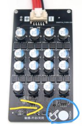
BTW there is an interesting looking new model with a touch on-off button (supplier said so). It seems it works the same way as you explained in the video but costs a few dollars less.
There is no picture of the backside as well no review on YouTube or elsewhere yet.
Product description:
The average battery voltage is higher than 3.25V and the balance is turned on
1500uF solid capacitor.
The accuracy is around 0.005V.
The maximum equalizing current is about 5A, (the maximum current is 5A, not the continuous current!) The voltage difference determines the equalizing current.
This equalizer is different from inductive equalization, which is energy transfer between adjacent batteries, and this equalizer is the energy transfer of the entire group of batteries. Size 4.8cmX4.6cm
Smarter Shopping, Better Living! Aliexpress.com

a.aliexpress.com


") Glad it helps.
Glad it helps.