Updates on testing HANKZOR's customized active balancer:
The kind customer agent i was always referring to was actually the very well known Nami many know here already. She does really a great job, they must be proud to have her!
So this is the information Nami supplied me with so far (she said after the weekend she can reply more accurately):
Only the voltage of B1 (cell 1) is measured. These are the specs of the chip which is doing that.
View attachment 99038
She wrote:
"Sorry, the engineer checked the resistance of the sample and found that the resistance used by this sample is 3.3V. As long as B1 is lower than 3.3V, it will stop. The voltage detection chip only detects the voltage of B1. When B1 is lower than 3.3V, it will stop, and when B1 is higher than 3.465v, it will restart. 3.3*1.05=3.465 startup"
As well:
"It can be made more accurately and needs to increase the cost"
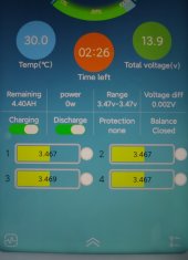
I checked and according to my new JBD BMS and pretty accurate RC3563 voltmeter which seconds the BMS measurement to the mV, my customized active balancer
starts if B1 is at 3.456V and stops again if B1 reaches 3.323V.