diy solar

diy solar

Am looking for some electrical code help

Am attempting to add images to helpfully better show what I'm up against.

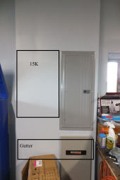
With Inside Wall, that is all the real estate I have to work with inside. While the inspector was willing to talk with me he said putting the inverter there was ok. Grid wire comes in from under slab and into ATS (all inside wall cavity). ATS then has wire run to main panel. Current generator wiring comes in through ICF wall and lands on left hand side of ATS inside of the wall.

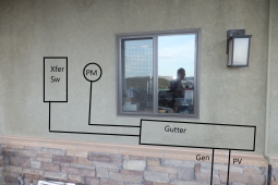
With Outside Wall, some variation on this is all I can come up with to work. I would prefer to not put the 15k out there cause early morning sun would fry the display.

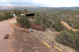
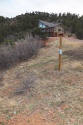
With Array 2, this is looking north. The last two years we have had occurrences of severe winds. Code says 120 mph and 30 psf snow load. I just lose 15 minutes of sun by not putting array on top of knoll. I like a little bit of wind protection by coming down on slope a bit. All there are clouds out there, if you look closely, one of those humps way out there is Pikes Peak.

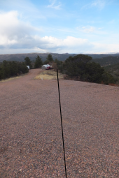
PV Conduit Run - that is a straight shot just to the east (right) of the leach field.

Last pic is close to looking directly south. Behind the house is the terrain that causes quit a bit of shading in the late afternoon in the winter. Our latitude here is 40 deg. I don't have any flat or close to flat terrain where I can otherwise put the array and still get reasonable sun exposure

If anyone sees something that makes this impossible to do from a big picture, just say so.

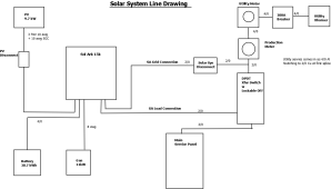
I'll noodle on doing a line diagram, but I think that will just be to much of a simplification.

Thanks for input.
 

Attachments

  • Inside wall.png
    Inside wall.png
    906.7 KB · Views: 17
  • Outside wall.png
    Outside wall.png
    2.1 MB · Views: 17
  • Array 2.png
    Array 2.png
    2.6 MB · Views: 17
  • PV Conduit Run.png
    PV Conduit Run.png
    1.2 MB · Views: 17
  • DSCF7235.JPG
    DSCF7235.JPG
    197.9 KB · Views: 17
Hey, thanks for the additional details. Sorry about checking on what you've worked on before wrt this type of project, I was just worried that the way your posts were written indicated going around in circles people that haven't remodeled before have hit.

I'm having problems with how to get the grid interface done in a code compliant method. I've estimated that I'm going to have $45k involved in this project - if I start. I don't want to start if I don't have reasonable confidence in completion. I'm not sure I'm at the 90% confidence level.

I've had several conversations with the co-op rep. As I had mentioned before, this co-op is not residential solar friendly. His basic reply is to send in the information they want to see, along with $500 and they will review. If they come up with a change that I can not physically execute in this house then I'm screwed - $500 gone. I'm retired. Already have wasted $200 on a consult that didn't result in anything actionable. Don't want to waste another $500 if this isn't gonna work.

Are they willing to specifically tell you where their jurisdiction ends? Are the POCO interconnect rules written down? That sounds like the biggest source of uncertainty. And you can decompose solving the problem to decoupled portions -- (1) make POCO happy (2) engineer the most costly variable part of this, which will probably be getting power back from the solar panels.

Compared to the project you described of bringing electrical service to your property. Around here, that part of a construction project is under the jurisdiction of the POCO (since it is wiring that needs to be done to their standards and is protected only by their fusing, etc), so it takes a good contractor to avoid making costly mistakes. But a solar contractor are flexible with what they do with the array as long as it matches the equipment & electrical specs approved by POCO.

Does your POCO offer net metering? If not, or the pay back is not really worth it, there is also the possibility of opting out of that, if it reduces regulations wrt your coop. This can be done by installing a zero export system or system that is physically separated from POCO wiring.

Depending on the interconnect and metering rules your POCO may ask for things like specific types and positioning of AC disconnect, production meter, ...

In my area:
POCO only looks at SLD (to look at point of interconnection), DC and AC size of the system, and what solar panels and grid tie inverters are to be connected. How things physically look beyond the inverter, and outside about 8 feet of their gas / electric service (there are restrictions in how equipment and conduit are laid out in this setback), are not their concern. Sometimes they will ask for more detailed drawings if new conduit or equipment encroach in the setback zone.

In fact for solar projects where the main panel does not need to be changed, the electric company only physically comes out to change out the meter for a smart meter.
 
Choosing equipment that supports an export limiter has another advantage. Backfeeding to the POCO requires the POCO to do engineering calculations to see if their infrastructure can handle the extra load from you sending electricity back to them. This can add time / add some cost & risk to the project if transformers need to be upgraded. (This isn't just an issue for residential installations, this is also a blocker for large scale generators). Ideally the POCO would be willing to do the engineering for you before you start a project...

If you choose equipment capable of export limiting then you have a backup plan if the engineering doesn't work out for backfeeding (EG, by limiting it below the level their infra supports without upgrades). I believe the SolArk has that feature, but I am not super familiar with it.

If you install batteries that can charge from grid, some POCOs also want to review that for various reasons (one reason being it shifts the power demands to different time of day), but I don't think that's something that would be helpful to get into right now.

BTW I don't think NEC is the best resource to understand POCO-side requirements. I've heard there's another doc for POCOs, but I don't think it's binding, it's more like recommendations? Hopefully someone pops in with the name of that doc.
 
How many MPPT inputs? If you had multiple PV orientations, then combining them at the array and using a single larger pair of wires would better utilize the copper. Maybe one pair of 8 awg, or 6 awg?
The SA15K has 3 MPPTs and each will accept two wire pairs. 10 awg is the max size that the PV terminals on the SA15K will accept. I also desire a bit of redundancy. If some hunter screws up and hits some part of the array, I'll still have two strings functional, until I can get out there and rewire to get the damaged one out of the string.
Technically, I think EGC should have ampacity for total array current x 1.56 (which yours might, depending on how over size 10 awg is for the current. Such a heavy ground wire would only matter if all strings were shorted and dumping their current into it, hopefully unlikely.
Quite frankly, I didn't get too rigorous in those calcs. I believe the SA15 can handle up to 26 amps per MPPT. So I pulled up an ampacity chart, saw that 10 awg was required for that current, then checked the voltage drop over 230', saw that it was less than 3% and said done. Am planning on ordering all the wire for the project from Wire and Cable Your Way (hope I didn't break a forum rule there). On a previous project I found I could only get the heavier cable by placing an order and waiting for them to get it in. Ordering on line I got the stuff here in 3 days I think a lot cheaper. I read somewhere that the EGC wire had to be at least the same awg as the largest current carrying conductor between pieces of equipment. I figured that would get determined when I sent the paperwork to the PoCo. If they didn't like 10 awg, the would tell me.
 
Are they willing to specifically tell you where their jurisdiction ends? Are the POCO interconnect rules written down? That sounds like the biggest source of uncertainty. And you can decompose solving the problem to decoupled portions -- (1) make POCO happy (2) engineer the most costly variable part of this, which will probably be getting power back from the solar panels.
Hey no worries on trying to figure out the experience level.

The PoCo has generic requirements written up and then the catch all phrase "must meet code". They require a disconnect means (figured a xfer switch with a locking off position would work) and I figured that would get worked out when they got my application. Also have to pull a state permit - so I've got three inspectors involved: county, state and PoCo. I doubt they will all be dancing to the same tune.

As I mentioned earlier, the boys out here are backwards. I have to install a separate production meter (in addition to the meter already on the service pedestal).

They do have net metering. I was originally planning on doing grid tied for the first winter to verify that there were no surprises. Well, I got a surprise when I mentioned that to the PoCo rep. If I went off grid they would pull the service pedestal and transformer that I paid to have put in - I'm not gonna throw away $10k. They gave me another option of having line retention for $180 a year fee. Currently just to be connected to their grid are going to be paying over $50 a month (fee increase next month) on top of the electricity we use. Things are a little out of the ordinary out here. The PoCo does not generate any electricity, other than a small farm that is limited to customers in a specific area. They buy all of their electricity from other utilities, mark it up and then sell it to us customers. We are on a branch circuit. A utility provider, pushes power up our way to a master meter about 4 miles away. After the master meter all of the customer circuits are owned by the PoCo. I think the PoCo has about 15000 total customers and our circuit may only have about 500 customers.

Their net metering agreement currently only pays 1.6 cents per kWh. And they want the residential power producer to be close to net zero. All though the PoCo guy said that they really don't enforce that aspect yet. The SA15K gives me the flexibility to conform to whatever vagaries (sp?) they may come up with in the future. I've estimated the break even point on this somewhere around year 20. So going solar is not cost efficient. There are times when our power quality is downrite bad. Flickering lights, UPS beeping numerous times a day, all clocks plugged into wall power no longer keep time. Some day something is gonna come down the line that will frag the control boards on some of the appliances.

I've gotten good price quotes on the panels, ground mount and the inverter and I guess the wire. As I've said before, I'm hung up on the interconnection. If I had a 10' long framed wall - no problem. If I didn't do something right, easy enough to pull things apart and redo. With what I've got, I've only got one shot at getting things right. That is where I'm hoping you guys can steer me in the right direction -or- tell me that it ain't gonna work.
 
Quite frankly, I didn't get too rigorous in those calcs. I believe the SA15 can handle up to 26 amps per MPPT. So I pulled up an ampacity chart, saw that 10 awg was required for that current, then checked the voltage drop over 230', saw that it was less than 3% and said done.
The current limit is much more important than the voltage drop limit.

Voltage drop only comes into play if it drops the voltage below the operating range of the MPPT. Well you're also wasting the power, but this is a cost-benefit tradeoff, not a functional one.

26 * 1.56 = 40.56 which blows way past the ampacity of #10. #10 ampacity is capped at 30A (60C column) after all derate. Derate is determined by NEC rules. How does 1.56 work?

1.25 is from PV being required to be treated as a continuous load
1.25 is to handle PV going over STC current rating. I don't know if NEC requires an additional multiplier for your higher altitude etc.

1.56 = 1.25 * 1.25

Derating includes
- Derate for number of Current carrying conductors (CCC). IIRC you wanted to pull multiple circuits so this will come into play. Without any derate you are limited to 19.2A, and it will quickly drop to 15.3A on the first derate tic (4-6 CCC @ 80%)
- Temperature limit for conduit. I think it's 90C for SCH40/80 in the installation location but I don't have a code/product reference.
- Ambient temperature

So you probably want to pull #8 copper or #6 aluminum, those are capped at 50A if there is only one circuit. If you have multiple circuits then 40A is more realistic.
 
They do have net metering. I was originally planning on doing grid tied for the first winter to verify that there were no surprises. Well, I got a surprise when I mentioned that to the PoCo rep. If I went off grid they would pull the service pedestal and transformer that I paid to have put in - I'm not gonna throw away $10k. They gave me another option of having line retention for $180 a year fee. Currently just to be connected to their grid are going to be paying over $50 a month (fee increase next month) on top of the electricity we use. Things are a little out of the ordinary out here. The PoCo does not generate any electricity, other than a small farm that is limited to customers in a specific area. They buy all of their electricity from other utilities, mark it up and then sell it to us customers. We are on a branch circuit. A utility provider, pushes power up our way to a master meter about 4 miles away. After the master meter all of the customer circuits are owned by the PoCo. I think the PoCo has about 15000 total customers and our circuit may only have about 500 customers.
OK, cool, you've done your homework and have the info necessary to figure out what the tradeoffs are here.

For the 20 year break-even. Wow, that is painful. What is your goal for the system, be able to cover most of your winter needs in a power outage? That kind of design goal really extends the break even point and initial costs.
 
I've gotten good price quotes on the panels, ground mount and the inverter and I guess the wire. As I've said before, I'm hung up on the interconnection. If I had a 10' long framed wall - no problem. If I didn't do something right, easy enough to pull things apart and redo. With what I've got, I've only got one shot at getting things right. That is where I'm hoping you guys can steer me in the right direction -or- tell me that it ain't gonna work.

Hmm. What about mounting the equipment in a solar shed, and then bringing it to the interconnection point on a single AC feeder? Then there is almost no equipment on that wall with limited space other than probably disconnect for that feeder.

Since a solar shed adds cost, maybe you can land the PV wires in a garage with some extra space on the walls, use that as the "shed", and bring a single AC feeder out to the interconnection point.

I assume you'll want batteries, there are a lot of fire safety code constraints on how they can be placed in living space, so garage / shed is easier to deal with. In a garage they mainly just need physical protection barrier from cars. Also with today's 48V systems as needed by SolArk, the batteries definitely have to be basically right next to the inverters.
 
One issue with putting the inverter farther away from the interconnection point is that it also requires the CTs needed for zero export to be farther away. For analog CTs (I think SolArk uses these) it is necessary to get manufacturer’s blessing for this distance, and be OK with the increased error from a longer run.

(There are also CTs that are connected to a power meter via short analog leads, which can then communicate to the inverter via a digital connection, which are immune to these issues but also have their own error sources)
 
The current limit is much more important than the voltage drop limit.
Man, you are shooting me down in flames!!!

The largest PV wire size that the SA15 accepts is 10 awg. I've seen PV wire runs of several hundred feet in videos. So where is my misunderstanding?

I think I'm still good with 10 awg. While the SA15 MPPT max amp rating is 26a, their panel design tool shows that for my config that Isc is 10.3 amps. So with a derated wire ampacity of 15.38 amps. I've got plenty of margin. I probably did this type of calcs a year ago when I decided 10 awg was sufficient. Now correct me if I'm wrong. I believe the array will be putting out more than rated power due to the site being at 8200'. Output voltage will be approximately the same, but there will be higher current. I bought a handheld solar meter over a year ago
and at noon on an absolutely clear day I saw about 1300 w/m2. I don't know if the meter was showing a valid number or not. But even if it is correct, I'm still good with the wire size and won't blow the MPPT. I've come across some sites that talk about a further derate for distance? Would this be true?

For the 20 year break-even. Wow, that is painful. What is your goal for the system, be able to cover most of your winter needs in a power outage? That kind of design goal really extends the break even point and initial costs.

Power quality from the POCO is poor. I've got the alarms turned on on one of the UPS's. It would alarm numerous times a day due to voltage and cycle variations. Lights in the house would flicker at times, wall powered clocks had their oscillators fritzed. Then there were the power outages. The first winter we were out here, we had an 8 hour outage on Christmas Eve. Think it was -20 outside. We have a well insulated new house and we only got down into the upper 50's at that time. The next spring I put in an 11kw Generac. A week ago we had a 12 hour long intermittent outage. Generator log showed that it ran on and off for about 10 hours. The utility that supplies power to the POCO replaced some hardware at a substation about 25 miles from our house. It took me a couple days to realize the the UPS wasn't beeping anymore. Did they fix a long standing problem that finally failed completely??? Two days ago we had another off/on/off/on.... power interruption. I went out and flipped the utility main off to force the generator to run. I let the gen run for 2 hours before I went down to check to see if the grid was back up. Neighbor texted me to say the power had just come back when I got back to the house. And we are once again getting occasional UPS cycling events. So I want to get clean power into the house before something expensive gets damaged. Also we are on a well, so no power, no water once the pressure tank gets depleted. I don't mind several hour runs on the generator, but if we are out for days - that will go through quite a bit of propane. Would rather get that energy from the sun. Yeah, it is kind of painful that the system will not break even until sometime after I'm dead.

Hmm. What about mounting the equipment in a solar shed, and then bringing it to the interconnection point on a single AC feeder? Then there is almost no equipment on that wall with limited space other than probably disconnect for that feeder.

Since a solar shed adds cost, maybe you can land the PV wires in a garage with some extra space on the walls, use that as the "shed", and bring a single AC feeder out to the interconnection point.

Can't put the batteries outside unless the shed is heated, would use up alot of the battery capacity just for heat. There is a battery manufacturer who builds some variation of an LFP that can be charged down to 0 deg F. But it has no cert. Also, no reasonable place to put a shed near the house.

I assume you'll want batteries, there are a lot of fire safety code constraints on how they can be placed in living space, so garage / shed is easier to deal with. In a garage they mainly just need physical protection barrier from cars. Also with today's 48V systems as needed by SolArk, the batteries definitely have to be basically right next to the inverters.

I had to educate the county inspector on LFP batteries. The state inspector indicated he wouldn't enforce the ESS constraints. I'm still a little concerned about putting 31 kWh (or more) of energy in an attached garage.
One issue with putting the inverter farther away from the interconnection point is that it also requires the CTs needed for zero export to be farther away. For analog CTs (I think SolArk uses these) it is necessary to get manufacturer’s blessing for this distance, and be OK with the increased error from a longer run.
The Sol-Ark install manual does not spec any maximum length on the CT leads. Says the leads can be extended using a twisted pair.

If any of the more knowledgeable people on this forum would come out and say that I have something that just can't be done (and explain why), I'd be ok with that.
 
Ok, I did an SLD. When putting it together I found out I had missed a disconnect - dammit, something else I have to find room for. I'm done for today...
 

Attachments

  • SLD.png
    SLD.png
    34.1 KB · Views: 23
The largest PV wire size that the SA15 accepts is 10 awg. I've seen PV wire runs of several hundred feet in videos. So where is my misunderstanding?

I just pulled up SA15 spec sheet for reference

1684194993787.png

Note there are 3 MPPT, 26A per MPPT, 2 strings per MPPT. I think the #10 limit is per STRING. And the SA can draw a maximum of 26A combined across the strings. Each MPPT operates at one voltage, so I think you can think of this as a built-in combiner, that saves you the trouble of adding an external combiner.

So if you split one MPPT evenly between the two strings, that's 13A each, so that is easily within the limit of #10.

I think I'm still good with 10 awg. While the SA15 MPPT max amp rating is 26a, their panel design tool shows that for my config that Isc is 10.3 amps. So with a derated wire ampacity of 15.38 amps. I've got plenty of margin. I probably did this type of calcs a year ago when I decided 10 awg was sufficient. Now correct me if I'm wrong. I believe the array will be putting out more than rated power due to the site being at 8200'. Output voltage will be approximately the same, but there will be higher current. I bought a handheld solar meter over a year ago
and at noon on an absolutely clear day I saw about 1300 w/m2. I don't know if the meter was showing a valid number or not. But even if it is correct, I'm still good with the wire size and won't blow the MPPT. I've come across some sites that talk about a further derate for distance? Would this be true?

I'm not sure how Isc is adjusted for light intensity, hopefully someone else knows the code for which Isc to use. I always assumed using STC was good enough.

I think the only distance based derate is for voltage drop. MPPT input is quite tolerant of voltage drop unless you're hovering just above 125V at the array. In that case you need to be pretty concerned about the voltage drop making the system plain not work. But using 125V would be pretty stupid in this setup for numerous reasons.

Power quality from the POCO is poor. I've got the alarms turned on on one of the UPS's. It would alarm numerous times a day due to voltage and cycle variations. Lights in the house would flicker at times, wall powered clocks had their oscillators fritzed. Then there were the power outages. The first winter we were out here, we had an 8 hour outage on Christmas Eve. Think it was -20 outside. We have a well insulated new house and we only got down into the upper 50's at that time. The next spring I put in an 11kw Generac. A week ago we had a 12 hour long intermittent outage. Generator log showed that it ran on and off for about 10 hours. The utility that supplies power to the POCO replaced some hardware at a substation about 25 miles from our house. It took me a couple days to realize the the UPS wasn't beeping anymore. Did they fix a long standing problem that finally failed completely??? Two days ago we had another off/on/off/on.... power interruption. I went out and flipped the utility main off to force the generator to run. I let the gen run for 2 hours before I went down to check to see if the grid was back up. Neighbor texted me to say the power had just come back when I got back to the house. And we are once again getting occasional UPS cycling events. So I want to get clean power into the house before something expensive gets damaged. Also we are on a well, so no power, no water once the pressure tank gets depleted. I don't mind several hour runs on the generator, but if we are out for days - that will go through quite a bit of propane. Would rather get that energy from the sun. Yeah, it is kind of painful that the system will not break even until sometime after I'm dead.

Hmm as you know for power quality and < 1 day outages you only need batteries. If the AC is really bad you can also switch to DC coupling it into your system via a Chargeverter-type setup, that is basically a big AC charger outputting 48V (AC coupling gets dicey if some of the power sources start misbehaving). Normally you would probably want to be AC coupled to grid because the DC coupling will add 15-20% inefficiency (AC->DC->AC), so potentially a "transfer switch" kind of setup to manually switch between the two modes might be a good idea.

Several days out -- yeah only choice is solar panels.

I think your connection fees / system decomm fees are ruthlessly designed to keep the POCO supported even if you go off grid (must have hired some consultants to figure out that math), so intuitively it feels like it will be hard to offset the system cost by generating some savings when the grid is up (I didn't do the math).

The Sol-Ark install manual does not spec any maximum length on the CT leads. Says the leads can be extended using a twisted pair.
That will probably be fine within a house sized situation. I think you'll have extra error (might be one sided because of the extra load for the CTs, might be higher symmetric noise), but since the CT is just to roughly keep export near zero I think it's fine. Probably a minor efficiency issue rather than a safety issue. And SA probably has a config where you can trim up/down the export limit if the CTs have some consistent error. You can install something like an Emporia or IotaWatt to get an independent reading of the export power (and those will have short CTs, and are within 1-2% of revenue grade accuracy).
 
Ok, I did an SLD. When putting it together I found out I had missed a disconnect - dammit, something else I have to find room for. I'm done for today...

Unusual to have disconnect on utility side of meter.

Production meter in series with utility meter, both read exactly the same thing? I would have thought transfer switch would land between the two meters. Production meter would still register consumption from grid through SolArk, doesn't split production/consumption like utility might want (not really possible with a hybrid.)

I'm not sure how Isc is adjusted for light intensity, hopefully someone else knows the code for which Isc to use. I always assumed using STC was good enough.

Fuses and wires to PV array sized for 1.56x Isc (STC)
I would argue 1.25x is sufficient for unfused PV or magnetic/hydraulic breaker, but code may not allow that.


For power quality, maybe SolArk can drop grid and make clean power whenever needed, but on-line UPS would be cleaner. That would need separate AC powered battery charger, and wouldn't let PV backfeed grid.
 
Several days out -- yeah only choice is solar panels.
… if you want to offset propane use for an indefinite outage.

Combining a generator with a battery system allows you to burn more efficiently, much as how it works on a prius. The generator can run at its optimal power point while recharging the battery. If it’s a good generator you can AC couple it and directly power any house loads that might come on, for a slight improvement in efficiency (battery charging just slows down a little).
 
Unusual to have disconnect on utility side of meter.
I thought that also. But the other day when the power was doing the off/on/off/on thing, I went outside and flipped the utility breaker off and the meter display went blank.

For power quality, maybe SolArk can drop grid and make clean power whenever needed, but on-line UPS would be cleaner. That would need separate AC powered battery charger, and wouldn't let PV backfeed grid.
My big picture plan was to have the SA power the house during the day while charging batteries, then when the PV went offline to run the house on batteries over nite, rinse and repeat each day. I would like to be able to power the house off of batteries for two days if weather conditions required. Then if absolutely necessary I would let the SA pull power off of the grid when I didn't want a lot of generator run time. I think SA says switching time is 10 ms.
 
Combining a generator with a battery system allows you to burn more efficiently, much as how it works on a prius. The generator can run at its optimal power point while recharging the battery. If it’s a good generator you can AC couple it and directly power any house loads that might come on, for a slight improvement in efficiency (battery charging just slows down a little).
It is an 11kw Generac and only intended for emergency short term use - not to run for days. I would have gone with a twin cylinder water cooled unit if I had wanted long term generator run times.
 
So if you split one MPPT evenly between the two strings, that's 13A each, so that is easily within the limit of #10.
I think we are on the same page. My plan was to run one string to each MPPT to start. Then, if any MPPT failed on me, I'd do two strings on one of the remaining MPPTs until I got the replacement parts. Trying to maintain some redundancy.

I need to cogitate on some of your other commentary a bit. First though, I need to go out and do some tree trimming since it is not raining today.
 
My big picture plan was to have the SA power the house during the day while charging batteries, then when the PV went offline to run the house on batteries over nite, rinse and repeat each day. I would like to be able to power the house off of batteries for two days if weather conditions required. Then if absolutely necessary I would let the SA pull power off of the grid when I didn't want a lot of generator run time. I think SA says switching time is 10 ms.

Relay transfer time will be fast, like my Sunny Island. Depending on instant blackout or a brownout, inverter may pass through out of range power for a while before it disconnects and picks up the load. Spikes that damage electronics can pass through, but extended periods of bad power what overheat motors etc. should be avoided.

Maybe unique to my system with multiple inverters paralleled, I have seen error codes, also tripped breakers. With single 200A breaker you may not have that problem.

If you want clean power to your loads, one option is to operate as on-line UPS. That is a battery charger fed from grid, and loads only see what inverter produces. Maybe that can be a configuration you switch to only when you expect or experience sustained power quality issues.

Rather than DC coupled battery charger, for my system I'm tempted to AC couple the grid to my system, by rectifying it and feeding in as if PV. Because my system is purely AC coupled.
 
Apologies. I've been doing a lot of web searching and haven't wrapped up several lines of investigation cause I'm still missing information.

Got access to an electronic copy of NEC 2020 and am trying to understand all of 690, 312, 314 and whatever related code sections I come across. Also came across solar365 which is dated but is helping point me to possibly relevant sections of the code.

Yesterday finished putting plane back together and completed the log book entries. But of course next few days will be low overcast and rain so can't do a maintenance check flight, figures. So I'll spend all day today studying electrical codes.
 
… if you want to offset propane use for an indefinite outage.

Combining a generator with a battery system allows you to burn more efficiently, much as how it works on a prius. The generator can run at its optimal power point while recharging the battery. If it’s a good generator you can AC couple it and directly power any house loads that might come on, for a slight improvement in efficiency (battery charging just slows down a little).
This. You want a generator charge backup if a "large outage" (on cloudy days) might be a thing.
 
Following up on a couple details.

One thing I learned with generators is that you can run generator signal wire in the same conduit as PV, but it needs to be V rated.
Yes, I remember reading that somewhere in the code.
Production meter in series with utility meter, both read exactly the same thing? I would have thought transfer switch would land between the two meters. Production meter would still register consumption from grid through SolArk, doesn't split production/consumption like utility might want (not really possible with a hybrid.)
I spoke with the POCO solar rep again last week. Hybrid inverters are "new" technology to him. He has heard of Sol-Ark, but isn't familiar with hybrids in general. I re-verified with him that they replace my current meter with a net meter and add a production meter. I pointed out to him that both meters will read the same back flow of current into the grid. I pointed out to him that the production meter will not "see" the power that the house is using from the PV. He then made the odd comment that I won't get credit for the power that the house is using from the PV. I told him that I had never expected to get credit for that and I thought that the POCO would want to get credit for the PV power that my house was using plus whatever I was pushing back in to the grid. His reply was that they were only interested in what I was pushing back into the grid. The conversation wasn't going anywhere useful. I'm just getting stuck for the cost of a meter can, conduit and wire for a production meter that doesn't do anything useful.

I'm still working on a code review post.
 
I keep getting bogged down in 690. Have also been trying to understand wireway vs raceway. Came across this gem from one source.

"A wireway is a raceway but a raceway is not necessarily a wireway." Hmmm, ok.

I've been going through the NEC collecting information that I think applies to my situation. Am dumping it here for comments.

110.26 Spaces About Electrical Equipment

Sol-Ark 15k to be mounted left of main service panel. 8x8” gutter wall mounted under Sol-Ark 15k and main panel. See Post #51, first image. There is 3’ of depth space in front of the service panel and 30” of horizontal clear space on either side of the Sol-Ark and service panel. I don’t think a gutter violates 110.26(A)(3). Comments?

Table 312.6(A) Minimum Wire-Bending Space at Terminals and Minimum Width of Wiring Gutters

Largest wire I will be dealing with is 4/0. I’m planning on using an 8x8” gutter. Minimum gutter width for 4/0 is 4”

376.22(A) Cross-Sectional Areas of Wireways

Using an 8x8” gutter, I won’t exceed the 20% requirement

376.23(A) Deflected Insulated Conductors

An 8x8” gutter meets Table 312.6(A) requirement.

376.23(B) Metal Wireways Used as Pull Boxes

I think I may have a problem with 314.28(A)(1) and 314.28(A)(2).

314.28(A)(1) Straight Pulls

I don’t think I will have any straight pulls. Wires will be coming in and leaving the gutter with 90 degree bends. Any comment?

314.28(A)(2) Angle or U Pulls, or Splices

Talks about a distance from raceway entry to an opposite wall needing to be 6 times the trade size of the largest raceway plus additions if there is a row of raceway entries. There will be 2” conduit between the bottom of the Sol-Ark and the top of the gutter. And there will be a row of 4. Requirement would indicate I would need 18” of distance between the raceway entry point on the top of the gutter and the opposite gutter wall. This does not seem reasonable. What am I not understanding?

376.56(A) Splices, Taps, and Power Distribution Blocks

Using an 8x8” gutter, I won’t exceed the 75% requirement.

Don’t know how to handle this situation

The service entry comes into the garage through the concrete floor via 3 4/0 al wires in PVC conduit. The conduit attaches to the bottom of a Generac ATS and then conduit is between the top of the ATS and the bottom of the main service panel to complete the wire path. The ATS and main service panel are flush mounted in a fake wall. The conduit is behind the drywall surface of the fake wall. The ATS will be removed as the Sol-Ark will control the generator. I have to get the 3 service wires into the exterior gutter. What is the best way to do that? Combination of pull box and conduit? Conduit only? Other method? Remember that the wall cavity is only 3.5” in depth and I have to have conduit between the outer and inner gutter and I only have 13” of horizontal space to work with. I don't see a way of getting this done.
 
I pointed out to him that the production meter will not "see" the power that the house is using from the PV. He then made the odd comment that I won't get credit for the power that the house is using from the PV. I told him that I had never expected to get credit for that and I thought that the POCO would want to get credit for the PV power that my house was using plus whatever I was pushing back in to the grid. His reply was that they were only interested in what I was pushing back into the grid. The conversation wasn't going anywhere useful. I'm just getting stuck for the cost of a meter can, conduit and wire for a production meter that doesn't do anything useful.
Yea, probably better to use fewer words sometimes. I should remember that rule myself.
 
@LBen , I'm in your same area of Colorado and I just failed my inspection for violating 690.31 D. I'm doing extensive research to verify that I need to basically tear everything apart from the moment the PV wire enters my power shed and replace it with metal conduit. I feel like I've watched a million install videos and haven't seen a single instance of someone using pure metal conduit from point of entry, although I'm sure they are out there somewhere. Obviously, my research lead me to this thread and I'm still confused about it. I probably looked like a deer in a headlight when he mentioned it because I was completely blindsided. I feel like my inspector has sworn to an oath to make my DIY life miserable. I am only able to get extremely vague pieces of information from him and those seem to make things even more confusing. I don't have all the complications of dealing with the grid or anything like that, but this 690.31 D is driving me crazy. We have power coming to the area in the next couple weeks, but I don't have any interest in connecting. Plus, the property is so far from the proposed power box (about 4,000ft), it doesn't make financial sense to even entertain tying into the grid. My ground solar array is about 200' from my power shed and I also had complications with various landscape obstructions and elevation issues. My biggest fear was not putting enough faith in the voltage loss calculators. Turns out, they are dead accurate. I used 10 AWG direct bury PV wire (pure copper) and I don't really see any noticeable loss from measuring at the array vs measuring at the disconnect in the power shed. Turns out, all I needed to worry about was 690.31 D, which I had no idea was even a thing. Anyways, where has your project landed you to date. Any updates?
 
Ok, you guys have kinda taken over my thread and I'm now more out in the weeds than when I started. I also need to figure out the quote function that every one is using.

First, PV and PVC - After reading and re-reading 690.31(D) it appears to me that it is legal to run PVC to the outside gutter and then the PV wire is in metal from the outer gutter, through the EMT, through the inner gutter and then into the SolArk. 690.31(D)'s paragraph title says "on or in a building" but the text only talks about "in" a building. It would appear to me that the "on" part only refers to roof mount systems. Mine will be a ground mount.

RSD - I thought that I had this one packed away a long time ago. Thought that I had read somewhere that ground mount systems did NOT require RSD. I've read 690.12 and that text is as clear as mud to me. Am I correct in believing for a ground mount array that an RSD is not required? In any case I plan on including a manual disconnect at the array. And then the SolArk has a PV disconnect switch on it and the PV wire enters the wall less than 3' from the SolArk. So I think I'm covered on the disconnect requirement?

As dcg9381 had queried about, Colorado adheres to NEC 2020, but the local state inspector (when he was willing to talk to me) said that certain aspects are not enforced. For example on the batteries, NEC 2020 says any single ESS cannot be more than 20kWh and I think that there is a total limit of 80 kWh and the individual ESS must be at least 30" apart. And then there is the 9450 or is it 9350 that says that the inverter/charger must be certified to work with a matched ESS. He said that he only looks for an NRTLS cert on the batts. I had also asked him if it was ok to put the SolArk to the side of the service panel. He said yes as long as there was access to the service panel. And then at that point he said that he only inspects and can't recommend anything. So my thought process is that if I understand how things must be done to be compliant with NEC 2020, then I will work to that goal. If I come up against an issue where there is a conflict, then I'll see if there is a work around.

The rural co-op rep told me that they have their own inspection criteria. He said that if the state passed the installation, that MOST LIKELY they would also pass it. I live in a rural, technically backwards county. I'd classify them as at least 10 years behind other places. The rural co-op does not like residential solar, but need the offsets for the state. They are into commercial solar that they then resell to the consumer. This has been an uphill battle. For the county inspector, I had to show proof that LFP batteries were relatively safe, did not require a vented cabinet and did not require a drain.

I had thought that I had reduced my list of issues/questions to just figuring out how to interface with the grid: gutter sizes, types of splices or power distribution blocks, wall pass throughs, most efficient way to wire the xfer switch and production meter, conduit fill, EGC, etc. But I think I'm doing a circle back on things I thought I had understood.

I'm gonna be out of pocket for the next couple of days, so may not be able to reply to anything during that time. I thank you all for your observations.
Look at the following exception from the 2020 NEC.
Exception: PV hazard control systems installed in accordance with 690.12(B)(2)(1) shall be permitted to be provided with or listed for use with nonmetallic enclosure(s), nonmetallic raceway(s), and cables other than Type MC metal-clad cable(s), at the point of penetration of the surface of the building to the PV hazard control actuator.

Wiring methods on or in buildings shall comply with the additional installation requirements in 690.31(D)(1) and (D)⁠(2).

Is your wiring that is coming into the building going to a disconnect prior to an inverter or the grid? If so, it most likely will meet the requirements of the exception. I would ask the inspector specifically about this.
 

diy solar

diy solar
Back
Top