diy solar

diy solar

Another "Review My Wiring" Thread: Fuses / Breakers / Wire Size / Grounding

MrM1

I'm Here, But I'm Not All There
Joined
Mar 1, 2021
Messages
2,422
Location
N. Central FL
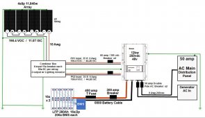
I'm old, It's Late, it's 1am and I am looking at the monitor with just one eye. Can you please talk a look at this wiring, fuse, breakers, ground etc diagram and give me some pointers? What have I missed?

I have not ordered any balance of system yet, just main components. So just now getting it planned out. This will be a fully Off-Grid dwelling and work barn. Installing a Growatt SPF 12kv DVM 250vdc inverter and over paneling with a 11,840w array 4s8p. The 8 series strings will join into a double combiner box that will run 2 PV inputs to the inverter. Each will be the parallel of 4 of the 8s strings. So PV1 will get 4s4p and PV2 will get 4s4p.

Plan is to house the Inverter, Main AC Distribution, Switchgear and Batteries in the solar shed. This will be within 20 ft of the Array. But if closer I could combine / tie all grounds together.

Please take a look to see if I missed anything or if anything looks out of balance. The PV breakers for the 2 PV in runs from the combiner are just going to be used as switches to turn the array off from inside the shed.

Trying to say as close to NEC 2017 as possible, But ...
- Do I need 4/0 for the battery cable?
- Are all other wires sized correctly for potential loads?
- Do I need #6 from the combiner? And to the main AC distribution?

Thanks in advance.
Mike
Final Wire Diagram.JPG
 
Last edited:
have you considered something like a victron shunt so you can accurately measure current flow?

your distance from array to combiner/equipment is around 20'..so that means your "wire distance" is actually 40' (both legs of the circuit).
you want to stay under 30a for 10awg. You may want to revisit your wire guage selection for that 60a circuit run.
You show 35ft of 6awg wire betweeen combiner and inverter, if that is the "one way distance", then you need to double it to size for cable losses..you always need to look at the total circuit distance. 6awg at 70 circuit feet still would be under 3% cable loss, that is one of those areas where you have to decide how much of your power you are willing to waste as heat. I always aim for a max of 1%, it is a personal choice until it hits a level where things get hot hehe

as an fyi is this single core copper wire of something like copper flex welding cable? high multicore wire needs to be derated, here is a link to a table that may help.
 
12000 ac watts / .85 conversion factor / 48 volts low cutoff = 294.117647059 service amps.
294.117647059 service amps / .8 fuse headroom = 367.647058824 fault amps.

Suggest you use a 400 amp class t fuse and a disconnect switch rated for 400 amps or better, unless you know of a breaker rated for the voltage, amperage and arc interrupt capacity of the circuit.
 
Looks Good to my eye in general.
I see no Surge / Lightning protection, this is NOT something I would omit. DC & AC side need to be covered.
Solar Panel Rail/Frame are independently grounded as they are non-electrical.
Primary AC Ground, you show two points to earth. Here that is a FAIL because that can actually create problems. ALWAYS defer to local/regional code requires as they do vary. For example, here you are only allowed to use Galvanised Ground Rods or Grounding Plates with Copper Wire. Some regions allow you to use a Well Casing as a ground while others do not.

Safety Tick: Genset Input
While not absolutely necessary, I do NOT trust the little breakers provided on ANY genset, life experience there... I feed my Samlex EVO Inverter/Charger via the Genset Input that takes 120VAC/30A, so therefore I use the L5:30 plug off the genset. From the L5:30 Wall Plug Input the 12/2 goes to a Square-D QO4L100S Box with Square-D QO140 40A *Charging at 75A draws 22A+/-1A/2500W+/-100W actual.

This is the L5:30 Wall Receptacle I installed on my Powerhouse but there are a wide assortments with various covers etc to fit needs.

Notes & a Suggestion regarding AC Genset Input.

Gensets vary a lot, their voltages do float up & down as does the Frequency in Hz. (Inverter gennies are much better) so you have to take into account the Hz fluctuations and also understand that while a Genset is powering your system, the "PASS THROUGH" is what the generator is outputting, so if it is Pure Sine great but ModSine or SquareWave (rare now) you can have issues. No Inverter will correct that ! (not with Passthrough). I have both Inverter & Non-Inverter gensets believe me, this is a PITA but you gotta know it and the consequence potential.

I strongly suggest that IF you add a 4-Slot Box & Breaker between Genset & Inverter/Charger then you also add an AC Metre as well. There are many versions and brands and some have RS485 & even BlueTooth if you want to get extravagant. T%hi swill let you see the Hz, Voltage etc at a glance and can also be used to keep a running tally of Volts/Amps/Watts incoming.
Link to possible metres to suit your use.

Hope it helps, Good Luck
 
have you considered something like a victron shunt so you can accurately measure current flow?
The Switchgear panel I am using will have a shunt, but not the monitoring app of the Victron, So I might do that.

your distance from array to combiner/equipment is around 20'..so that means your "wire distance" is actually 40' (both legs of the circuit).
you want to stay under 30a for 10awg. You may want to revisit your wire guage selection for that 60a circuit run.
You show 35ft of 6awg wire betweeen combiner and inverter, if that is the "one way distance", then you need to double it to size for cable losses..you always need to look at the total circuit distance. 6awg at 70 circuit feet still would be under 3% cable loss, that is one of those areas where you have to decide how much of your power you are willing to waste as heat. I always aim for a max of 1%, it is a personal choice until it hits a level where things get hot hehe

Array to combiner on any one string will never exceed 12 amps on any one string. Each String will have it's own +/- run to the combiner.

The 60amp 300vdc breaker is only for a switch, but is it over sized for the wire?

I do not understand the concept of "one way distance"? This would be for power coming in off the array only. But I will have 2 runs +/-, one for each PV input on the Inverter/SCC. So the amp load on each input (PV1 and PV2) wire runs would be 45 amps each Max ISC. Operational current for each string is 10.52 amps, so my 4 strings (each PV input) would be closer to 42 amps.

I do not want too much heat, but 3% losses will not be a problem. We are overpaneling the array larger than the inverter needs, so at 7000 wattts max (3500 watts on each PV input) for the SCCs at 200vdc input , the current the SCC will actually max out at for usage is 18 amps per PV input.

Thanks for your thoughts
 
12000 ac watts / .85 conversion factor / 48 volts low cutoff = 294.117647059 service amps.
294.117647059 service amps / .8 fuse headroom = 367.647058824 fault amps.

Suggest you use a 400 amp class t fuse and a disconnect switch rated for 400 amps or better, unless you know of a breaker rated for the voltage, amperage and arc interrupt capacity of the circuit.
Thanks, I'll hit the searches again for those. But the issue with using a 300a T Fuse and a 250a breaker would be that it would just blow / trip at hi surge loads???
 
Last edited:
Looks Good to my eye in general.
I see no Surge / Lightning protection, this is NOT something I would omit. DC & AC side need to be covered.
Solar Panel Rail/Frame are independently grounded as they are non-electrical.
Primary AC Ground, you show two points to earth. Here that is a FAIL because that can actually create problems. ALWAYS defer to local/regional code requires as they do vary. For example, here you are only allowed to use Galvanised Ground Rods or Grounding Plates with Copper Wire. Some regions allow you to use a Well Casing as a ground while others do not.
There is Lightening protection in the 8 to 2 combiner from Watts247 that we are using, they say the combiner must be grounded though. Not sure if that should go with the array/rails or the DC/AC gear. But I was going to thru in a couple Midnite Solar arrestees in the appropriate locations.

The 2 points of the primary AC ground are 2 points. Sorry, I should have shown 1 point there. I know better than that. It was late and I just drew it wrong. But do I ground the chassis of the Inverter to that main ground too?

I would need to research the Genset input further. I have not thought that one thru very well yet
 
As I do not own that Make/Model of inverter system, I cannot address the question regarding how to ground it. Their docs would clearly indicate ground points.
 
Safety Tick: Genset Input
While not absolutely necessary, I do NOT trust the little breakers provided on ANY genset, life experience there... I feed my Samlex EVO Inverter/Charger via the Genset Input that takes 120VAC/30A, so therefore I use the L5:30 plug off the genset. From the L5:30 Wall Plug Input the 12/2 goes to a Square-D QO4L100S Box with Square-D QO140 40A *Charging at 75A draws 22A+/-1A/2500W+/-100W actual.
I was planning on using a 50 amp double pole DIN rail AC breaker from Midnite Solar for the generator input. Would that be enough?
 
Thanks, I'll hit the searches again for those. But the issue with using a 300a T Fuse and a 250a breaker would be that it would just blow / trip at hi surge loads???

Not even surge current.
294.117647059 service amps is the full bore continuous output for the inverter and will trip the 250 amp breaker pretty quickly.
The 300 amp fuse would have zip headroom and you would possibly get nuisance trips on it as soon as you solved the breaker problem.

4/0 pure copper wire with insulation rated for 105C is good for 400 amps and change.
The over-current protection device's primary job is to protect the wire.
The first over-current protection device off the battery positive terminal also protects the battery from a dead short.
The best guess I have heard on this forum for the dead short current of a 48 volt nominal LFP battery is ~20000 amps.
This is why most of us recommend a class t fuse for the "doomsday" position.

Also, typically higher rated fuses have less resistance, which is nice.
 
Last edited:
Also, Fun Facts about the Growatt

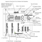
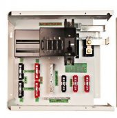
I have a Schneider Conext SW at my house, and have it mounted up with a Midnite Solar E-Panel. Nice and Clean. As I was looking at the E-panel, it occurred to me, the E-Panel for the SW might work for the Growatt 12kw. Measuring it up, it fits nearly perfectly. Plan is to use an SW E-panel turned sideways. This gives me multiple connection busbars, Several DIN rail and Panel Breaker spaces, a shunt, etc. I would only need to change the main battery connect bars to short 4/0 cable because the battery connect might not line up.
Problem is they only come with a max 250 amp breaker. I'm checking to see if midnite has a larger DC breaker.

But it would be very clean and give me tons of options.

Growatt - Epanel 1.JPG

Benefits:

E-Panel pic4.JPG

E-panel pic1.JPG
 
Last edited:
Not even surge current.
294.117647059 service amps is the full bore continuous output for the inverter and will trip the 250 amp breaker pretty quickly.
Sadly MidNite Solar's largest breaker is a 250a dc. Not sure where to source something that size
 
I got 2 400A fuses, 1 for each series string, and 1 switch. I will put the switch after the fuses and after the busbars just before Going into the inverter
 
I'll use 2/0 from the battery post/stud to the studs I have purchased that will mount on the plywood compression frames...about 8 inches long 2/0 cables. Then I'll use 4/0 from the series string post, thru the fuse to the busbars and on thru the switch to the inverter.

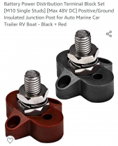
I'm using positive and negative studs mounted on the plywood compression frames so that if /when I disconnect series packs I'm not removing lugs from battery terminals putting stress on the terminals.

Once top balanced and packs built I pretty much won't have to touch the battery posts again.

Capture+_2021-10-25-21-19-48~2.png
 
Back
Top