diy solar

diy solar

Apparent/reactive power while off-grid: Victron vs SMA

Consumerbot3418

Fitting square pegs into round holes... for fun?
Joined
Jan 17, 2021
Messages
202
Location
Midwest
While running off-grid for the better part of a year now, I've been monitoring energy use carefully. What I've overlooked, until now, is reactive power. I'm trying to wrap my head around it, but I think I've got the basic gist of it: capacitance or inductance as a load leads or lags the phase. What I don't fully understand is where that reactive power "goes". My understanding is that it's dissipated as heat in both the appliance and the inverters. Further, I've come to believe/understand that SMA inverters have active Power Factor Correction, while Victron inverters do not.

I'm now trying to ascertain just how much energy I'm losing, and whether or not it's even worth the concern. I've got multiple inverter-based compressor appliances in the house: window AC/heat pumps and a refrigerator. These have a poor power factor, but due to their variable speed, PFC can't be performed with simple capacitors or inductors, but needs to be done with active PFC circuitry, as far as I understand.

What I'd like to ask: is all of the reactive power provided by the inverters lost to heat? This page describes how SMA inverters can correct a site's power factor to avoid charges from the utility. Since I'm off-grid, I'm mainly concerned about wasting energy and depleting batteries. I'm wondering if the Sunny Boy or Sunny Islands are actually doing active PFC, and if so, whether it's saving energy, or merely improving power quality. I've got a kill-a-watt that shows VA and PF, as well as a o-scope, but I'm not sure how to check or confirm. Sunny Boy instant values contain a reactive power measurement in the "AC Meter" section, if memory serves, but it's always blank, which I'm guessing is because I don't have an SMA meter installed.

Hopefully @Hedges and @RCinFLA won't mind me tagging them to get their attention... Thanks in advance!
 
While running off-grid for the better part of a year now, I've been monitoring energy use carefully. What I've overlooked, until now, is reactive power. I'm trying to wrap my head around it, but I think I've got the basic gist of it: capacitance or inductance as a load leads or lags the phase. What I don't fully understand is where that reactive power "goes".

Stored, similar to energy stored in a spring or in a moving mass. Then thrown back at the grid (or battery inverter). Cycles between drawing power and returning power. So long as your inverter can handle that, no huge problem. That is what a "4 quadrant" amplifier can do.

But I've seen some UPS which seemed to dissipate the power thrown back at them. It registered 350W load, but with load fed through a power transformer that jumped to 900W

My understanding is that it's dissipated as heat in both the appliance and the inverters.

Power factor < 1.0 increases loss, but not all the difference between "Apparent Power" and "Reactive Power" is lost as heat.

Voltage available is the same, so higher apparent power involves higher current. Power dissipated in wires, breakers, MOSFETS is due to I^2R and causes heating, so higher current causes more heating, proportional to square of current.

Further, I've come to believe/understand that SMA inverters have active Power Factor Correction, while Victron inverters do not.

I think it can only be enabled and set by command. GT PV inverter has no knowledge of power factor at grid (or battery inverter) connection so can't adjust in response.


The manual for my TriPower mentions "Q on Demand"


"Controlling the Q(V) Characteristic Curve with Integrated Plant Control

The Sunny Tripower inverter can provide reactive power to the utility grid with the "Integrated Plant Control" function. The grid operator specifies via which process the inverter is to provide reactive power to the utility grid. In many cases, the grid operator will request control in accordance with a Q(V) characteristic curve. SMA inverters with "Integrated Plant Control" are capable of reproducing this Q(V) characteristic curve without performing any measurement at the grid-connection point. The inverter can automatically compensate for equipment installed between the inverter and the grid-connection point.

The function "Integrated Plant Control" is not capable of compensating for irregular or fluctuating reactive power demands due to, for example, connected machinery, if the machinery is connected between the inverters and the gridconnection point. If the machinery is connected directly at the grid-connection point, it is possible to dynamically determine the additional reactive power demand of the machines using additional measurement equipment and then to provide this value as an offset to the Q(V) control."

Says some aspect can be automatically detected and compensated by those inverters, but for the most part you have to measure power factor and program the inverter.

While "Volt-Var" function of UL-1741-SA inverters may be this sort of PFC, TriPower can be told to keep operating at night of PV input goes to zero. It just acts as a programmable PFC device, therefore "Q on demand 24/7"

I'm now trying to ascertain just how much energy I'm losing, and whether or not it's even worth the concern.

I think it is only in GT PV inverters to benefit the utility. And to allow higher power delivery to grid. It seems to be part of UL-1741-SA or SB.


I've got multiple inverter-based compressor appliances in the house: window AC/heat pumps and a refrigerator. These have a poor power factor, but due to their variable speed, PFC can't be performed with simple capacitors or inductors, but needs to be done with active PFC circuitry, as far as I understand.

Different kind of < 1.0 PF
Inductors delay sine-wave current 90 degrees. Capacitors advance sine-wave current 90 degrees.
(Motors I've measured had a different, more complicated waveform.)

Cheap VFD have a rectifier/capacitor front end. If you simply fed rectifier into a resistive load, would still have in-phase sine-wave current and PF ` ~ 1.0 (diode adds voltage drop and non-linear resistance). But rectified into capacitor, there is zero current until line voltage exceeds capacitor voltage. Then a gulp of current, then no current when voltage again drops below capacitor voltage.

3rd plot top green trace is current drawn by VFD ("V" represents amps).
(Lower red trace is AC current sensor on battery cable.)

https://diysolarforum.com/threads/battery-ripple-current.22431/

The brief higher current into VFD causes more heating of wire and thermal breaker, because power loss and heating is proportional to square of current. If half the time, twice the current, then 4x the heating times 1/2 the time = 2x power dissipation. The breaker would be able to carry 0.71 times as much power before tripping. With 20A breaker, 2 HP pump eventually trips it at full speed. When 15A breaker fed induction motor, it never tripped.

What I'd like to ask: is all of the reactive power provided by the inverters lost to heat?

As described above, higher power factor of reactive load means higher current, which causes higher loss. But mostly, the power stored in "reactive" loads such as inductors and capacitors is returned to source as out of phase current.

This page describes how SMA inverters can correct a site's power factor to avoid charges from the utility. Since I'm off-grid, I'm mainly concerned about wasting energy and depleting batteries. I'm wondering if the Sunny Boy or Sunny Islands are actually doing active PFC, and if so, whether it's saving energy, or merely improving power quality. I've got a kill-a-watt that shows VA and PF, as well as a o-scope, but I'm not sure how to check or confirm. Sunny Boy instant values contain a reactive power measurement in the "AC Meter" section, if memory serves, but it's always blank, which I'm guessing is because I don't have an SMA meter installed.

GT PV inverters normally deliver current 180 degrees out of phase with voltage (compare to resistive load 0 degrees out of phase), so they deliver power rather than absorbing. The SMA inverters can be programmed to deliver leading or lagging current, simulating a capacitor or inductor in parallel. That could compensate for other loads in the facility, making power factor closer to 1.0. Primary benefit to owner would be reducing charges imposed by utility. It reduces current and therefore loss in utility power lines.

It should increase power available to facility through main breaker. Assuming GT PV inverter is on a separate branch circuit, it doesn't change PF and current in any facility wires so doesn't save power inside the facility.

With an alternative energy system, PFC would reduce current drawn from inverter, leaving more current to be drawn by loads. Inverters might be rated in "W", but really have a "VA" limit due to maximum current they can deliver. If some of the current is reactive power, that reduces available wattage. The inverter might have a separate actual wattage limit due to boost converter of HF design (also current limit of battery and/or PV.)


Hopefully @Hedges and @RCinFLA won't mind me tagging them to get their attention... Thanks in advance!

My Sunny Islands are able to power the VFD, also induction motor in AC (second picture, triangular current waveform for some reason.)

However, when the Sunny Boy GT PV inverters wake up and see the voltage waveform (I still need to capture that and view), they think they have an internal fault and don't connect to deliver power.

I tried paralleling an unloaded induction motor thinking it would provide PFC for the VFD, but current waveform at inverter unchanged.
For now I don't operate it offgrid. Plan is to add PFC modules in front of VFD (those draw sine wave current and deliver 360VDC).
Better quality VFD have PFC inside.

Besides VFD, typical power transformers draw non-sinusoidal current and have poor PF at least under light load.
Pictures in following link are transformer secondary backfed with line voltage, Primary fed at 1/2 rated line voltage, Primary fed at normal rated line voltage. Notice how current shoots up at peak, badly distorting sine wave. That is due to saturation, inductance drops off. Feeding primary works better than backfeeding secondary, and at half voltage it is much closer to an ideal transformer.

 
Last edited:
Active power factor correction in SMA is primarily targeted to improve power factor so a facility with a lot of DER generation doesn’t screw itself over by getting assessed a large bill due to going outside the power quality range that the utility requires.
 
Thanks for the detailed reply, and the links--I'm often reluctant to start a new post to ask a question. Odds are, it's been asked and answered already...

Power factor < 1.0 increases loss, but not all the difference between "Apparent Power" and "Reactive Power" is lost as heat.

Voltage available is the same, so higher apparent power involves higher current. Power dissipated in wires, breakers, MOSFETS is due to I^2R and causes heating, so higher current causes more heating, proportional to square of current.
But mostly, the power stored in "reactive" loads such as inductors and capacitors is returned to source as out of phase current.
This makes sense, but it raises the question "then what?"

I saw this post of yours, @Hedges , which ends with:
What does your battery inverter do with current shoved into it?? Does it store the power in capacitors, or does it get burned up as heat?
That gets to the very root of my question. In my specific case, I have 2x Sunny Islands combined with 7.7kW of Sunny Boy feeding through a pair of Victron Multiplus. I wonder if the Sunny Boy is "recycling" the reactive power during daytime, or if the Multi or Sunny Islands are doing that. And if so, what are my actual losses?

I guess I could start with a simple experiment, run some of these poor PF loads in evening using Multis only, and check the DC-AC efficiency, as @AntronX did here? He said inverter efficiency only dropped 5% on a 400W load with 0.8 PF. So only around 25% of reactive power lost, I guess. If my case is similar, I guess it's not so bad as to justify looking for replacement appliances.

Still may be worth exploring other PFC options. This thread (Synchronous Condensers in an off grid system) is certainly interesting!
 
I believe the reactive power will not be burned anywhere (setting aside resistive losses in wiring and mosfets ), but unless the inverter quotes both a W and VA number, you can assume that the W spec is for a high PF close to 1, and if your PF deviates from that you should treat the W rating as VA. This with poor power factor, you are sort of increasing the “overpaneling” level of your setup. EG the effective wattage (active power) that your inverter can output is decreased.

Note that victron is weird, they quote both and I believe W is lower than VA because they assume, like, PF 0.8. Why? Dunno.

FWIW you can always call up the manufacturer and ask.
 
Overall I think this is mostly good as an brain training exercise, I doubt there’s a practical issue here.

I don’t think it matters wrt wasting battery KWh. You’ll still get the same mileage.

It matters if the inverters cannot handle the running VA your motors demand.

It matters if you run the motors at the same time as clipping solar production, it’ll clip more.

It may matter if your charger/inverter (the type that can do both roles at the same time) is maxed out sooner than you expect, so instead of having spare capacity to charge that capacity is diverted to cycling reactive power. This part I’m not so sure about because it’s possible in some designs something other than the FETs take the hit. Maybe the LF transformer?

If you have an grid tie inverter, Volt Var from the grid profile will force your inverters to give up some of their VA handling capability to inject Var into the grid.

Note: when you start measuring this, there could well be some parts of your system that report wrong metrics. I’m not sure if VA vs W vs PF reporting is implemented diligently in all hardware.
 
I wonder if the Sunny Boy is "recycling" the reactive power during daytime, or if the Multi or Sunny Islands are doing that. And if so, what are my actual losses?

I don't think Sunny Boy is doing anything except delivering current in-phase with voltage. Unless it has received a command to do Volt-VAr.

Sunny Island I think sources or sinks current whenever it has to, trying to maintain sine wave voltage. I haven't looked yet with VFD operating, but I think it is less than completely successful because voltage is what my Sunny Boys would see, and they got upset. With a transformer connected, I think I saw it draw 15 VA based on clamp ammeter but increase in battery current showed only 7W consumed.

What MultiPlus does, I don't know. But if it handles motors well then it must deal with it nicely.

I guess I could start with a simple experiment, run some of these poor PF loads in evening using Multis only, and check the DC-AC efficiency, as @AntronX did here?

Let's see what you get.
I'm not an expert on the subject, just taking a few measurements and applying theory. I've learned a lot about magnetics the last couple years.
 
Low frequency hybrid inverters are inherently bi-directional and will source or sink current to battery based on AC voltage regulation. Difference between battery discharging and charging is just the inverter AC output voltage regulation level.

The regulation is based on low frequency 60 Hz feedback control so there is a little time response lag in adjusting inverter's PWM sequence to change battery voltage to inverter AC output voltage regulation.

If the inverter is not allowed to export back to grid, as the AC grid voltage varies the inverter AC voltage will be adjusted to match grid voltage to prevent continuous backflow to grid. A small time period glitch in grid voltage may show up in battery current pull or push glitch with the feedback reaction time limitation of inverter.

On high frequency inverters the effects of poor power factor are handled by HV DC filter capacitors on the output of battery to HV DC boost converter. Poor power factor can cause stability issues in this battery to HV DC converter.

Inverter losses are based on load current, so the amount of inverter loss is based on VA loading not true watts. This is same for inverters, generators, or AC transformers.

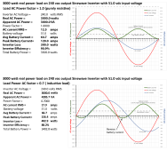
There are primarily two causes of poor power factor.

One is inductive AC motor loads that has sinewave AC current but out of phase with AC voltage.

Inverter power factor waveform.png

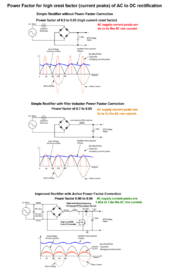
Second, which is more of an issue, is caused by simple rectifier-capacitor filter AC to DC power supplies which draw high peak current only at the peaks of AC sinewave voltage. Such devices have a short peak current draw up to 3-9 times the equivalent RMS current. Mini-split air conditioners are common cause of high current crest factor, short peak current loads.

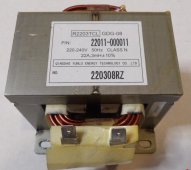
Some mini-split air conditioners have an inductor choke between rectifier and filter capacitor which reduces the peak current by about 50%. With the choke, the AC power factor is improved from about 0.6 to about 0.8. This makes them have a similar power factor to single phase AC induction motors.

Mini Split AC PF choke.jpg


Full Wave rectified Power Factor diagram.png

California Rule 21 has forced some inverters to provide AC load power factor correction at AC input during AC pass-through. It reduces inverter efficiency. It makes more sense to correct the poor power factor at the device AC load then have a supplementing inverter do it.
 
Last edited:

diy solar

diy solar
Back
Top