diy solar

diy solar

transformer excitation current - isolation transformer used as auto-transformer

Hedges

I See Electromagnetic Fields!
Joined
Mar 28, 2020
Messages
20,682
So you think you can backfeed a transformer secondary, either as step-up or as auto-transformer?
Turns out these things aren't so ideal and reversible as one might expect. It isn't just the greater inrush (primary is often wound outside secondary to reduce inrush current), but also idle current is much higher driving secondary.

My attempt to use a 3-phase 480 to 120/208Y transformer for step-up didn't go well.


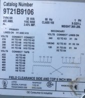
I've now picked up a 25 kVA 240/480V to 120/240V transformer. I plan to use it for isolation, 240V in to 120/240V out with derived neutral (which will be grounded.)
This sort of transformer is quite common, and could serve as auto-transformer for people who need to get a neutral for middle of 220V inverter, or split-phase from a 120V inverter.
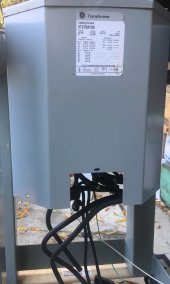
Transforer 25kVA IMG_3214.jpg

Transformer label IMG_3215.jpg

The obvious way to use it is with the two 120V windings connected in series. I fed 120V (125V, actually) into one winding and the other did produce 125V as well, and 250V across the two. Output voltage would drop a couple percent under load, maybe 5% if 12.5 kVA being transferred.

It was making noise under no-load. Clamp ammeter showed 10A (1250 VA apparent power).
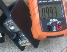
Current 125 into 120 secondary winding IMG_3221.jpg

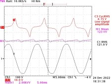
Scope, calculating V x I and averaging, showed 263 W consumed (and 9 A rms.)

Notice in particular the severe peak in current (upper trace C3) as the winding is driven into saturation. At its normal operating voltage, but backfed.
Voltage shown in lower trace C1, power middle trace M1.
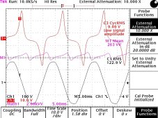
GE 9T21B9106 120V into 120-240 winings 121722 1407.jpg

By instead feeding 120V into one of the 240V primary windings, connected in series, performance was much nicer.
Only 0.36A drawn, 45W apparent power. Voltage on second winding was still same 125V as applied.
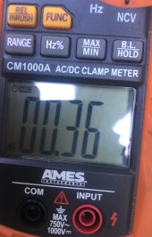
Current 125 into 240 primary winding IMG_3219.jpg

Scope shows 0.617 A RMS, and 57 W dissipated. (More real than apparent power? Perhaps measurement error or drift over time?)
Since this configuration is applying 120V to one of two 240V windings (which are intended to carry about 50A each), expect only 6 kW to be available on second winding.

Note the current waveform isn't nearly as ugly as when secondary was back driven, although still not a nice sine wave.
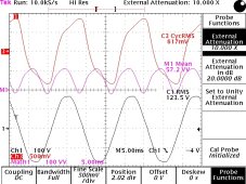
GE 9T21B9106 120V into 240-480 winings 121722 1347.jpg

Makes me wonder how the transformer would behave if excited by voltage on primary, but power delivered from GT PV inverter on secondary.
I'm still learning about transformers.
 
Last edited:
Here's what it looks like with proper 240V driven into 240V winding. 4.15A draw
Still a peaky waveform, like a Hershey's kiss.
Note the current is 90 degrees out of phse with voltage, inductive.
(perhaps some inverters would be unhappy getting their current shoved back at them.)


GE 9T21B9106 240V into 240-480 winings 122422 1549.jpg
 
Continuing from here: https://diysolarforum.com/threads/c...ation-questions-sol-ark-15k.55888/post-730587

But I know it to be incorrect. In an auto-transformer, neutral lead carries current equal to sum of L1 and L2 current. And those are always equal. (Two within how well real transformer behaves ideal.)

You can prove this to yourself with Kirchoff's current law, by considering power in and out, with SPICE, or bench test with an ammeter. Just so long as you don't approach the issue with a closed mind and only accept answers that N = L1 - L2.

An isolation transformer, N = L1 - L2. But backfeed it as well (e.g. from PV) and the answer then lies somewhere between N = L1 - L2 and N = L1 + L2.

Hmm, I'm going to have to work it out. I definitely buy that the current through the coils (and therefore how many VAs you are subjecting the transformer to) will be different in the AT vs isolation transformer case. I'm not sure about the behavior of the current, it should always obey Kirchoff's law. I think the N = L1-L2 and N = L1+L2 discrepancy might be an artifact of how current signs are being handled.

I think this is a fine convention for sign of current.

-- L1 ->
|
|- N ->
|
-- L2 <-

L2 = L1 + N, right? That's just Kirchoff's law. Sure, it's possible something counterintuitive will pop out of that because when the power comes from the primary and there is no backfeed all those currents are non-negative.
 
Continuing from here: https://diysolarforum.com/threads/c...ation-questions-sol-ark-15k.55888/post-730587


I think the N = L1-L2 and N = L1+L2 discrepancy might be an artifact of how current signs are being handled.

nope. I can make |N| = |L1| + |L2|
in a sense that is just the sign (and direction of current flow), but most people would think if L1 and L2 currents are equal, N current is zero. In the secondary of an isolation transformer, with only primary driving, that is true. Not when center-tapped secondary is driven; then it is an auto-transformer.

Just Kirchoff's Current Law.

In an isolation transformer, current flows in L1, through windings, out L2 (after subtracting some taken by N if any imbalance.)
In an auto-transformer, current flows in L1 and due to magnetic coupling, also flows in L2. And of course sum flows out N. One is driven by applied voltage, other overcomes applied voltage and drives current in opposite direction.

Key thing to understand is that no current flows through a transformer winding unless an equal and opposite current flows through another winding. (well, current X turn count have to be equal and opposite.)

For an isolation transformer, no current flows in the primary unless a load on the secondary accepts current. (Ignoring the no-load current I captured on scope in earlier posts.)
 
These aren't designed, per se, to be driven with PWM generated waveforms. So if driven by a HF inverter, the core losses are going to be larger than one might think.
 
That would be an issue if you used such a transformer in the construction of an inverter, and then filtered the output.

I'm only trying to use the transformer outside of an inverter. Any inverter ought to drive waveforms of low harmonic distortion. Some, I'm sure, are uglier than others.

I've done most of my transformer testing with grid feeding it, but I used Sunny Island when I needed 3-phase. It seems driving one phase of an E-core 3-phase transformer is not the thing to do.
 
OK, getting back to whether there's an NEC booboo about neutral current on service conductors.

Yeah I worked it out on paper here with the same answer you got. 200A on the neutral.

Though if your PV cuts out the MSP breaker will trip since your load needs 200A from the grid. So in theory the load calculations provide a measure of defense. Assuming load calculations are required to be done against service size if you rely on the utility to balance your 240V generation
 
Now, it's not mentioned in 705.12, but couldn't the autotransformer be considered a power source? Sort of.

And then the neutral sizing for the feeder / tap rule needs to take this into account.

(Yes, I now agree the code is deficient, at least in not having a section to talk about which side the neutral current comes from. there are plenty of ESS SLD where the neutral comes from the same side as the service, and the opposite side from the PV)
 
If you are driving external transformer from inverters the funky waveform is likely due to the PWM filtering on inverter output. The shunt filter capacitor (2-4 uF range) on inverter output side is interacting with the transformer excitation base inductance.

It should improve with greater load.
 
So consider a bunch of customers on a 120/240V feed from utility's pole pig.
Hot day, they all have 120V window AC on, all on same phase. Instead of overloading utility transformer and blowing a fuse, all us rooftop PV producers deliver extra power to L1 and L2.
Pole pig delivers neutral current 2x L1 and L2. Too much current for the wire, and too much coupling for the core?

(Yes, I now agree the code is deficient, at least in not having a section to talk about which side the neutral current comes from. there are plenty of ESS SLD where the neutral comes from the same side as the service, and the opposite side from the PV)

If 120% rule is followed, your utility drop and busbar gets 1.2 x 1.2 = 1.4x as much temperature rise as intended. Not the end of the world.
Only an issue with excessive imbalance in 120V loads.

Utility transformer and transmission lines may be at risk, depending on PV penetration.
 
Pole pig delivers neutral current 2x L1 and L2. Too much current for the wire, and too much coupling for the core?
Suppose we delete the PV from existence. Wouldn't the neutral anyway need to be sized enough for that amount of 120V window AC?

If 120% rule is followed, your utility drop and busbar gets 1.2 x 1.2 = 1.4x as much temperature rise as intended. Not the end of the world.
Only an issue with excessive imbalance in 120V loads.

Sure if you follow the 120% rule, there is a limit to how much current your bus bars and neutral bars will be subjected to in a worst case imbalance. 120% * busbar.

There are other parts of 705.12 (feeder sections) that allow a lot more current onto the neutral, I think 200%. So perhaps they need to have their own version of 120% rule.
 
Suppose we delete the PV from existence. Wouldn't the neutral anyway need to be sized enough for that amount of 120V window AC?

I think utility transformer and transmission lines are sized assuming customers aren't all at 100% or even main breaker rating. And neutral would be no larger than L1 or L2.
Too much drawn by consumers could overload the circuit. Apparently some entire neighborhoods have only 25kVA transformer. i.d. 100A 240V.

Are fuses on secondary? Maybe there is also a disconnect on primary?
If secondary L1 and L2 are fused, N is protected assuming no PV or other backfeed.
(If primary fused, would have to be limited to 50% of VA rating for 240V, to protect same size wires for 120V.)
 
Utility transformers are unlikely to be at risk due to high PV penetration. The primary issue is utility loses control on load demand management.

Cal rule 21 is trying to manage some of these issues. Many parts I agree with but some items, like using GT inverters for power factor correction I do not agree with.

Issue is air conditioner usage has grown a lot creating worse residential loads power factor. If you want to improve power factor on grid then regulate power factor of appliances.

GT inverters cannot do much for high peak current rectifier-capacitor based power supplies in most U.S. variable speed inverter compressors.

My expensive Samsung variable speed inverter compressor refrig has a terrible 0.60-0.65 power factor. Samsung saves a few bucks on manufacturing cost for appliances in U.S. that does not have regulations for poor residential power factor. It would not be allowed in EU.

Poor grid distribution load power factor is pissing away 4-7% of generated power and taxing distribution grid.
 
Too much drawn by consumers could overload the circuit. Apparently some entire neighborhoods have only 25kVA transformer. i.d. 100A 240V.

What I mean is, the overload condition would have happened without PV too. PV just makes it more complex to analyze / add more failure modes.

Utility probably now needs to monitor L1 L2 N (inspection, real-time telemetry) where previously they only need to monitor L1 L2 and infer N.

Apparently some entire neighborhoods have only 25kVA transformer. i.d. 100A 240V.
I've seen that number kicked around... but that sort of also implies that the EV penetration in those neighborhoods is pretty low, otherwise we would have heard about more exploded transformers from overnight charging.

Or, the kVA rating for that equipment has a healthy safety margin, IE can take it for N days / deteriorated lifespan until the lineworkers come to replace it.
 
using GT inverters for power factor correction I do not agree with

Yeah, I've been in some convos about that. It's sort of a hidden tax (equipment wear and tear from the ~10%? higher thermal stress) as a devil's bargain for being allowed to feed in to the grid.

My expensive Samsung variable speed inverter compressor refrig has a terrible 0.60-0.65 power factor. Samsung saves a few bucks on manufacturing cost for appliances in U.S. that does not have regulations for poor residential power factor
Oh wow that is terrible. I thought Energy Star had PF requirements? OTOH, fridge isn't THAT big of a load.

Though Energy Star is voluntary. Also, when I was young and naive I thought Energy Star existing meant non-energy star stuff was also dragged along to be decent. Nah... not the case for a lot of appliances.
 
Cal rule 21 is trying to manage some of these issues. Many parts I agree with but some items, like using GT inverters for power factor correction I do not agree with.

"Integrated Plant Control and Q on Demand 24/7 SUNNY TRIPOWER / SUNNY HIGHPOWER"


Issue is air conditioner usage has grown a lot creating worse residential loads power factor. If you want to improve power factor on grid then regulate power factor of appliances.

GT inverters cannot do much for high peak current rectifier-capacitor based power supplies in most U.S. variable speed inverter compressors.

That may be. Not sure if they can help with that, or just compensate for phase shift due to L or C.

My expensive Samsung variable speed inverter compressor refrig has a terrible 0.60-0.65 power factor. Samsung saves a few bucks on manufacturing cost for appliances in U.S. that does not have regulations for poor residential power factor. It would not be allowed in EU.

I agree, would like front-end SMPS synthesizing a "real" resistive load.
 
What I mean is, the overload condition would have happened without PV too. PV just makes it more complex to analyze / add more failure modes.

Without PV, blows the fuse.
With PV, I could blow the wire (melt the insulation). Or maybe the transformer.
 
Yeah, I've been in some convos about that. It's sort of a hidden tax (equipment wear and tear from the ~10%? higher thermal stress) as a devil's bargain for being allowed to feed in to the grid.

I saw some analysis that said a small imaginary component allowed much greater real component of power delivered. So a small price to pay to not throttle? I think it was about not exceeding max voltage.

PF correction ought to be the responsibility of the culprit.
 
"Integrated Plant Control and Q on Demand 24/7 SUNNY TRIPOWER / SUNNY HIGHPOWER"

https://files.sma.de/downloads/IPC-QoD24-7-STP-TI-en-17.pdf

Oh, in this mode the power factor correction directly helps the customer. Because they can escape power quality charges, which go up in probability significantly if generating PV as 100% active power.

In the case I think RCinFLA is talking about, you as a residential grid tie customer are donating the Q correction to the grid with no compensation. Other than not being allowed to grid tie unless you have a Rule 21 compliant smart inverter, which includes this.
 
I saw some analysis that said a small imaginary component allowed much greater real component of power delivered. So a small price to pay to not throttle? I think it was about not exceeding max voltage.

Yes, I think Volt-Var kicks in at a voltage level close to where Volt-Watt will start curtailing.

And Volt-Var activating will most likely push the grid down in voltage. Which means you don't have to trigger Volt-Watt (which will reduce your generation income).

OTOH, Volt-Var activating may take away from the available circuit ampacity/apparent power budget on your inverter that you need to maximize your active power output (which is what you get paid for). So maybe someone other than you gets to generate the power now that the grid voltage has been pulled back down.

It's somewhat "communist" feeling.

EDIT: cleaned up some wording
 
Last edited:
Back
Top