diy solar

diy solar

Astrophography build

Quick update.

Cells have arrived!
Decided to move up to a Meanwell 24v 340w power supply instead of the 12v. Ronogy can handle up to 25v so I will adjust it down to 21.
Have a lighted latching push button that I will test when the cells are charged. There is a spot on the BMS for it.
Been fighting with the 3d printer the past couple days. That blue material was just crap. Switched over to a different spool and it's printing perfectly now. Have about 18 hours left for the main case.
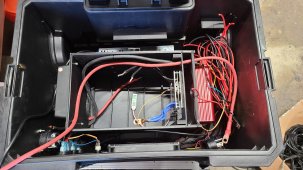
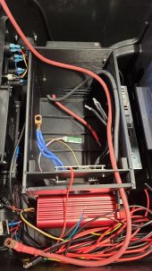
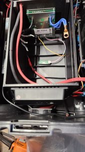
Made some adjustments to the case. Made it a little more modular so upgrading cells shouldn't be an issue in the future. Also made it shorter and moved the BMS to the right side instead of the top.
Other parts are being printed also. Some are completed and some will get redone after some adjustments.
Got one of the fans installed, waiting for a fan guard for the other.

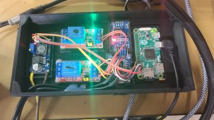
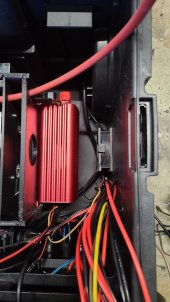
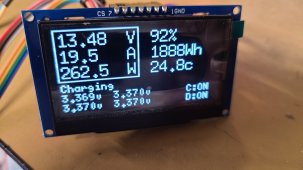
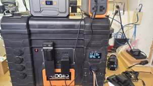
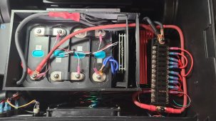
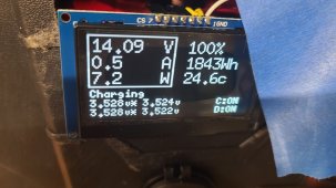
Have it all hooked up on the bench. BMS is working as I expected and the power monitor is working as well. Need to get some 10ga or 8ga for some of the wiring, but I expected that. Have 4ga for the main power wires and plenty of 12ga for all the outlets.

I'll try to get some new pictures tomorrow once a few more things get printed.
 
Dont know what I was thinking. Complete brain fart. Using a 24v stepped down lower isn't as good as using a 12v. Home moment I guess.

With the correct power supply I'm not putting in about 28 amp.
 
Have things setup on the bench right now. Top balancing was done last night. Spent some time today with the settings in the BMS. Have a capacity test going on right now with what the normal load would be. Numbers are matching up with my initial calculations with load & run time. Should get 30+ hours at least and most likely closer to 40. Will vary depending on the weather cause the cameras cool themselves below the ambient temp so sometimes they will need more power, other times not so much.

It is looking though like I will need to break out a serial port and get into the Renogy Wanderer to see what the charge settings are. Waiting to hear from their support on another possible issue/concern with the charge controller. Since this is my 1st time working with LifePo4, charge controllers not sure if it is normal for the PV terminals to have battery voltage on them when there is nothing hooked up to the PV terminals. Concerned that this is normal and having ports exposed with power, even though it is only 12v. I would have expected there to be no voltage on the PV side. Dont want to spend or waste the money on their BT device given the reports I have read on how bad it is , even more so when it cost more then the controller does.

Voltage diff on discharge is sitting at 0.003v. 4 hours in and voltage is back and forth between 13.3 & 13.2 (assume the BMS is rounding numbers up/down) or the app is. The time left though has changed drastically over 4 hours....39 hours, 3 hours, 4 hours, 22, hours....in that order. The % though has been steady and matches with the DC lcd monitor/shunt.

This is the chart I used for setting the voltages on the monitor. If anyone knows of a better one to use let me know. https://diysolarforum.com/threads/c...d-voltage-for-each-percent.35438/#post-445340
 

Attachments

  • arduino raspberry.jpg
    arduino raspberry.jpg
    306.9 KB · Views: 3
Past few days has been spent doing some capacity testing & charging. Few updates

1) 12v AC/DC power supply died. It was a cheap one so not totally unexpected. Going to use the 24v 15a Mean Well one I have. It's half the high so that will help, plus it is actually a good quality one.
2) Renogy Wanderer has failed per Renogy. They tried to tell me that it was normal to have voltage on the PV terminals even if nothing is connected to them. Called BS on that as that could cause issues is anyone were to touch a wet open port. They are replacing it, should be here today.
3) Made some changes to the cell case. Made it shorter and moved the BMS to the front instead of top. Few other tweaks, but minor. Printed out in 32 hours. Had a good number of layer separation which happens with ABS sometimes. Plastic weld should take care of that.
4) Ditched the DC monitor. It just wouldn't show SOC well. Plus the shut would have to be almost right next to the display which I didn't want. Just dont think those are good enough to use for these types of cells.
5) Found someone who took the Overkill Arduino code and modified it to work with a LCD. Going to go that route, I think it's better anyway and it will get the SOC, voltage, etc directly from the BMS. Would be a little cheaper too. Have a mount already for it to go and will fit in the hole I cut for the above monitor. It will use the same uart port as the BT so it will be one or the other, but see next item.
6) Will be able to swap the BT & Arduino LCD back and forth if I need to. Have a wire harness made to go from the Arduino to the wire harness from the BT device. This will let me swap these if I need to. I'll put some double sided velcro on the BT module and keep it in the case.
7) Have the back brackets for the top shelf installed
8) BMS bracket is made and will slide into the case with the cells. This will let me remove it if I need to.
9) Shelf for the fuse box is currently printing, will be put in today
10) Wiring to all the outlets, fan, Raspberry have all been run. Temp sensors are also installed
11) Side fans are installed, waiting for the guard to come in today for one of them.
12) Inverter, SCC & AC/DC power supply are all mounted to the case.

Should have all the parts in today to finish this up. Still need to design & print a couple other pieces like covers, retention blocks and then get the cell case bolted down in the box.

Couple pictures of progress so far. Will have more tomorrow.
 

Attachments

  • 20220319_150445.jpg
    20220319_150445.jpg
    322.3 KB · Views: 1
  • 20220319_150454.jpg
    20220319_150454.jpg
    143.2 KB · Views: 0
  • 20220319_150459.jpg
    20220319_150459.jpg
    115.9 KB · Views: 0
  • 20220319_150531.jpg
    20220319_150531.jpg
    130.9 KB · Views: 1
4) Ditched the DC monitor. It just wouldn't show SOC well. Plus the shut would have to be almost right next to the display which I didn't want. Just dont think those are good enough to use for these types of cells.
Yea, was not worth the effort. I never trusted mine and always double checked against voltage. Voltage was my truth so ended up ditching shunt.

Your new display is awesome. Not available in red? The white light nazis will shame you…
 
lol. Found it in green & white. They can piss off. hahahaha.

Havent played with the contrast settings but I'm really liking it so far. Here is a link to the display project https://github.com/vagueDirector/ArduinoXiaoxiangSmartBMSDisplay

I might look at a way to put it to sleep & wake up with a button but not really needed I think.

Putting things on hold for a day or 2. Power supply was getting pretty warm. Have a way to solve that but have another idea that I need to see if it will work. If so then it will get a little easier for charging.
 
Been keeping the spreedsheet updated on the 1st page. Still see this as something someone could do for under $850. 2 biggest expense are the cells & the BMS. I'm sure you could go cheaper on the BMS if you get one from Aliexpress or go with 100ah cells instead of 160ah or spend a little more if you wanted 205 or 230ah cells.

Figure I have gone through 2 spools of material printing out parts, redesigning & reprinting. If do this suggest using spare rolls or colors you have on hand that you dont care about during the prototyping phase.

Changed up the fuse panel to one with a single row to allow more spacing. Also replacing the fans with ones that provide more CFM. The ones I am currently using are ones that I had sitting around. Changing out fans to hopefully solve the heat problem when changing. PS was getting too warm to my liking.

Made some adjustments to the arduino code that controls the fans. It uses DS18B20 sensors which sometimes give false readings. Added code to ignore these. Code is attached if anyone wants to use it. Has 2 relays connected to it that control the 2 fans. One was originally going to go on the BMS but I'm thinking I dont need it. If I do I can always add another sensor & relay in the future. At full charging my top temp is 50.25 deg C. Existing fans are able to keep the temps at this level.

Have continued to some capacity & charge testing. Everything is still in line with my original calculations. I can get a 26 hours with my typical load of 2 scopes & gear. Charge time is around 7 hours for a full charge which I dont expect to do much of, if ever.

Love the Arduino display but having problems with the way the original creator wired things. He had it so that it would display constantly. Since I am using a switch to turn on/off the BMS output and the wire it is originally wired means it would be on 24x7 this wont work for this application. works as it should if I wire it up with my TTL usb adapter & plugged into the USB ports on the inverter, but would like to have this connected to the fuse panel instead so it is fused & turns off when output is cut.

My goal is to have the physical items all done in the next 2 days. last thing to go in will be the fuse panel and then bolting down the cell box to the case. I need to make the fuse panel removable (at least to move it out of the way) in case I need to remove the main "box" that has everything else attached to it, replace the fans, etc.
 
Last edited:
Build is 95% done. Have a lid printing for the cell case and then need to secure the brackets to the main case for the top shelf and then get the LCD & bracket secured.

Something I have seen so far.
BMS will always be drawing power even if you turn off discharge. With the discharge switched off there is still about 3v that goes through. Suspect this is so that the BMS is always working and the BT is always available. This means I should still install a main disconnect switch besides the one I am using connected to the BMS. Just can't find one that I like so far. Dont like the big bulky ones.

I have solved the heat issue with the AC/DC charger. Replaced the 80mm fans I have on each side and they are now keeping the temps within 8deg of ambient inside the case while charging. If I had used a bigger case I could of done some baffling or made a duct but there just isn't enough room with how I have things.

Inverter is working great. It's a true sine wave even though it's only a 300w unit. Nice that it has USB ports cause that is what the Arduino that controls the fans is connected to. So it & the fans will only run when discharge is enabled.

The LCD is working great as well. Wish the guy was still active so I could buy him a beer. It will also indicate balancing on the cells when it is charging.

Fuse panel is removable if I need to get the main box out. Fans are replaceable as well. The outlet leads are longer then they need to be but going to leave them for now vs cutting back a few inches.

Currently charging a few misc batteries and a couple of the smaller portable units I have & use. Charge cable, power strip, extra fuses & BT module all go in the top on the shelf.

Skies might finally be clear Friday night and if so it will get put through it's paces out in the field. Things have a tendency to crop up when in actual use vs theory or bench testing.
 

Attachments

  • 20220323_130954.jpg
    20220323_130954.jpg
    349.4 KB · Views: 1
  • 20220322_223555.jpg
    20220322_223555.jpg
    323.4 KB · Views: 1
  • 20220322_223639.jpg
    20220322_223639.jpg
    292.6 KB · Views: 2
  • 20220322_224724.jpg
    20220322_224724.jpg
    212.5 KB · Views: 2
  • 20220323_131758.jpg
    20220323_131758.jpg
    315.1 KB · Views: 2
Weight came in a little higher then I was expecting at 51lb.

My power consumption with no devices connected (only Raspberry Zero, Fan Arduino, 2 relays & LCD is right at .9amp/12.2w so I need to add this into my spreedsheet.

Just my main scope/gear I should get at least 29hour
2nd scope & gear (no heaters or cooled camera) 35 hours
Combined 16 hours

I wont be using both at the same time for a majority of sessions, will be either or. When going to really dark sites though I expect I will be using both and most likely some additional gear but those instances will be fewer. Plus I still will carry my (2) small 240wh units which support pass through charging so I can always have the gear connected to them and then charge those with the 2k unit giving even more time.

Now the hunt is on for a decent foldable solar panel.
 
Here is the latest config for the fan control. Has 2 fans and will act as it's own wifi access point so you can upload config updates over the air.

Eventually I will get this to act as a web server also where you can change the temp settings on the fly as well as see what the temps are through the web interface.
 

Attachments

  • Arduino_Multiple_Fan_Control_ota.txt
    3.8 KB · Views: 0
Have new code working on the fan control now. It turns on at 35 deg & off at 25 deg. Takes 1:35 to cool down & 2:45 to get back up to temp. This means the fans aren't running the entire time it is charging. Also have it displaying to a web interface so the temps are displayed. Arduino acts as an access point and has OTA ability. Means the code can be adjusted on the fly if necessary. Expect during the summer time the temps may have to be changed some but it's working much better. Fans both draw about 1.2amp which should only run during charging but it can be set to run the fans going using the 2nd temp sensor. I have the 2nd sensors settings adjusted higher & lower then the one by the power supply for the charger. Can even add a 3rd sensor and put by the BMS (was original plan) if I wanted to, just a pain to get to the arduino & solder a new sensor in.

Will be going out in the field on Friday for a full test run, most likely with 2 scopes as well.
 
Back
Top