diy solar

diy solar

Basic off grid BMS design, for 38 series, 100ah cells; your thoughts wanted.

BruceM

New Member
Joined
Jul 8, 2021
Messages
59
I'm hoping to pick the brains of folks with some hands on experience with LiFePo4 for off grid power regarding balancing options for a new BMS design for a bare cell lithium replacement for my off grid 120VDC battery bank (100ah). I'm a EE/CS guy, retired, and have used my own design 120VDC system for the last 12 years using wet lead-calcium type "marine deep cycle" batteries, getting about 4.5 years per set of ten 12V 110 ah batteries. I also have my own design inverter so have 120/240 AC for well pumping, laundry, and shop use. My system uses my own custom BMS/battery balancer and PV charge regulator. I recently found Will's fantastic youtube series and want to design a new system for LiFePo4 cells,

What I lack is first hand experience with LiFeP04 cells particularly with the issue of how much ongoing passive balancing current is needed. Because I'll need 39 batteries in series for my nominal 120V bank operating between 3.05 and 3.4 V. I'd like to keep things as simple as practical. At present I'm have two options in consideration.

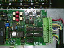
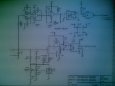
The simplest option is a passive, top side 3.4v shunt voltage regulator for each cell, and to mod my custom PV regulator to a fixed voltage to maintain the cells at a constant 3.4V plus a tiny bit t so they just barely self regulate. Since the cells would be held at 3.4V for 5+ hours every day, this seems to me, an utter lithium novice, that this might do the trick of balancing at 100ma or less. Large balance current just means more board, heat sinking and wiring cost. My current 12V battery regulator is quite involved, with temperature compensation, 3 voltage levels of regulation, up to 3 amp (linear) shunt current and shunt current feedback to the BMS so charge current is limited as needed. I'd like to keep things as simple as I can for the 38 (ouch) LiFePo4 cell regulators.

I can add low and high cell voltage with a bussed capacitively coupled signal for emergency alarm.

I wonder if this will provide acceptable balance over time with low cost LiFePo4 batteries, and or how much current the shunt regulator should be able to sink?
My typical charge rate is very low, limited by sun angle in the early morning; my DOD is quite low. My maximum charge rate is 16 amps. My maximum discharge rate is 20amps. Remember this is at 120VDC nominal.

I'm not interesting in the commercial higher voltage bank balancers for both cost and conducted EMI reasons. The are designed for high current applications and mine is a modest off grid home power.

As a retired EE, I must say I've been consistently impressed at Will's videos. The care and skill to make things technically accurate will still understandable to the non-engineer lay people is VERY impressive. I usually frequently cringe at bloopers in "technical" information videos, but never for Wil'l's channel. Bravo!

BruceM
 
Welcome to the forum.

Typical passive BMS balancers may only provide 30-70mA of balance current. 100mA would probably work well and 200mA might be even better given the atypical cell count.

The need for balancing depends 1000% on the quality of your cells. There can be wild variations within any cell group. All may meet data sheet, but their self-discharge may be different enough to make passive balancing a challenge.

For the $90 commodity cells, more is better. For the $125 matched and batched cells should be good with minimal balancing.
 
Hi Snoobler,
Thanks for the note and kind welcome!

It's VERY helpful to know that there is wild variation the bargain cells.

I'd be buying all new 100ah cells from a single vendor on Aliexpress, but from your note, that may require a lot more cells to get 39 roughly matched ones. I saw Will testing budget Aliexpress cells with passive balancers and thought I might as well. Can anyone suggest a "brand" that will be useful for my application? I'm only using the upper middle 25% of capacity, and for the top side balancer would be charging, limiting each cell to the 3.4V level for several hours every day. Charge rate is typically very low, a few amps in the early morning.

I have complete freedom to increase the top side balancer current to 1 amp or more, and also to switch to a full time passive balancer of any amp capacity if absolutely needed. (Preferably with a simplifying cheat to compare cell voltage to the average cell voltage instead of the lowest.)

I don't have a feel for how much drift will happen with budget cells when being operated with low charge/discharge currents and only 20% DOD. I suppose there are very few designers/experimenters with that sort of experience, but I hope to hear from one!

Bruce
 
Your ideas are sound. Keep in mind that you don’t have to disconnect the batteries if you get a single cell going high that the balancing can’t contain. You only need to stop charging. In time if the same cell continually goes high you can manually connect a power resistor (or lamp etc) across this cell to bring it in line with the others.

If you aren’t using all the capacity of your bank the cells can be quite imbalanced and it doesn’t matter.

All the commercial BMS units i have include temperature sensors on the balance resistors.

I know of plenty of people with similar setups to what you propose - it works fine.
 
As far as I can tell, the only thing you need to worry about with your proposal is differences in the cell's charge efficiency, and self discharge rate. If your system top balances, and you draw out 20 amp hours, some cells may be at 80% SoC while a very weak one might might be down to 60% SoC. This would be a very worst case, and yet it is not really a problem. When the system charges back up, the weak cell is also going to charge faster, and they should all come very close to full charge when 20 amp hours is put back in to the cells. If some cells are reaching their full charge knee area early, then the balancer can kick in and bleed off some charge current from the high cells. The balancing bleed off should be triggered when a cell is more than your desired delta above the lowest cell. For LFP cells, I would suggest when the cells are above 3.35 volts, you start to connect a passive blead current to any cell that is 20 millivolts (0.02 volts) higher. If the cells are all within 20 millivolts, then no balance current is needed. 100 milliamps should do the trick, but watch the action for a few cycles, and if you end up with a cell still running, you may need to do a better top balance, or increase the balance current. 100 ma of balance current when you are charging at 10 amps, is only 1%, so the cells need to be within 1% match for that to be enough. But if you also have the CV absorb voltage set fairly low, like 3.4 volts per cell, then the current will taper down, and the balancer will have more authority to pull the cells into balance.

My main 14S Li NMC battery bank is using a JK BMS with 2 amps of active balance current. But that 2 amps can only pull or push power to a single cell at any given time. If only one cell is drifting high, it can pull 2 amps from it, but for a bit less than half the time, so call it 1 amp average. It will then spend the other half of the time, pushing that 2 amps into the lowest cells. With 38 cells in series, having just a single 2 amp balance like this might not be as effective. If it has to blead down 4 high cells, it will only pull on each one, 1/8th of the time, so 2/8 = 0.25 amps or 250 ma. Still reasonable, but you get the idea. I am still quite amazed at how well my pack is staying in balance. My 2 amp active balancing hardly ever activates, and I have the cell delta voltage dialed down to just 6 mv from lowest to highest. Whenever I connect to my BMS, I typically see the cell delta voltage sitting at 2 to 4 mv, and the balancer is not active.

There is one feature I don't have, that you should add if you can. If any single cell does hit 3.55 or 3.60 volts, reduce the charge current. With the number of cells you have in series, it is quite easy for a runner cell to get way out while the total pack voltage is still low. If your normal full charge voltage is 3.4 volts per cell, with 38 in series, you are at 129.2 volts before the charger would go into absorb CV mode. But what if just one cell starts to run? So one cell hits 3.7 volts, Oops. 129.2 - 3.7 = 125.5 volts / 37 more cells = 3.392 volts on all the rest. If you are charging at 10 amps, and one cell starts to run, the balancer kicks on, and even if you pull a full amp, you still have 9 amps charging the runaway cell. This could get bad. Most BMS units are only able to just shut off charging. If you can ramp it down as the rogue cell starts to go high, the balancer can keep up while the rest of the cells still get some charge going in.

Once the pack does reach a good "Top Balance" it should hold well until a cell starts to get weak, but this is something you need to watch when the system first starts up.

One idea I had, but I have not tried it yet....
If you capacity test all of your cells, you can add a few small cells in parallel with the ones that measure less capacity. You can easily find 1.5 to 7 amp hour LFP cells. So if a cell measures a little low, just parallel a suitable small cell to get the correct total capacity. So if a weak 100 AH cell measures 95 AH. Add a 5 AH cell in parallel, and in theory, it will take about 5% of the charge and discharge current, and the two together is back to 100 AH. I have not tested this idea, but I see no reason why it would not work. When people group a bunch of random 18650 cells, they try to match up total groups that come up to the same total capacity, this is the same basic idea. Look at a Tesla car battery, and imagine just adding 1 or 2 more cells to adjust the capacity of each P group.
 
These cells have a pretty flat voltage characteristic over most of the usable range, but things become dramatic in a big way at both ends.
Above around 3.45v the charging voltage will begin to rise at an ever increasing rate. In other words, in a series charging situation one cell can "take off" ahead of others, and the cell voltage can very easily rise to destructuve levels very quickly.

To counteract that, some kind of voltage clamp might be needed that can safely dissipate the entire charging current. And that is a rather tall order.

While you plan to charge to only 3.4v per cell average, that should work fine while the cells are new and reasonably balanced. But over time that 50mV safety margin may prove insufficient from preventing one or more cells from "taking off" and self destructing.

After several years experimenting with a thirty cell (100v nominal) string, and trying many different battery management systems, my advice would be as follows:

First thing would be a continuous monitoring of individual cell voltages. That can best be done by switching cells individually across a common cell monitoring bus with optically isolated solid state switches. Use the same voltmeter to monitor every cell. Its the only way to pick accurate relative cell to cell voltage differences down to the millivolt level. I use LAA127 switches. (slow but very robust)

If you can display the individual voltages on a video screen as histogram bars, that is extremely helpful.

Use the measured individual cell voltages to trigger a voltage disconnect system.. I use a circuit breaker fitted with a shunt trip coil if any individual cell goes beyond undervoltage or overvoltage limits. Also use the individual cell voltages to turn the cell balancing resistors on and off.

The simplest strategy is to compare each cell voltage to the average, and discharge all that are above the average. The currents Snoobler mentioned earlier are in the right range. Over months and years it takes surprisingly little, if balancing is a continuous ongoing process.

Its a queer thing, but watching individual cell voltages rise and fall on a video screen, they seem to vary from day to day. One day a certain cell will streak ahead of the others during charging. But the following day the same cell might be quite sluggish, and a different cell takes the lead. I have no idea why this happens.

The whole system can be software driven or built in analog hardware. My display also records max and min cell voltages as well as real time voltage, and it has been extremely useful for trying out various cell balancing strategies.

Thirty 60Ah Wiston cells fit very nicely into a standard filing cabinet drawer behind the video monitor.
There is room for another additional 6Kwh in the lower drawer but have not fitted them yet
 

Attachments

  • 2019-01-14_0001.jpg
    2019-01-14_0001.jpg
    1 MB · Views: 18
  • 2018-10-10_0009.jpg
    2018-10-10_0009.jpg
    864.1 KB · Views: 19
  • 2019-02-04_0001.jpg
    2019-02-04_0001.jpg
    1.2 MB · Views: 19
  • 2018-10-10_0007.jpg
    2018-10-10_0007.jpg
    875.6 KB · Views: 19
Thank you Tom and Gary!
Gary mentioned this:

"There is one feature I don't have, that you should add if you can. If ll does hit 3.55 or 3.60 volts, reduce the charge current." (With a clear explanation following.)

I use just that sort of scheme with the topside passive linear shunt regulator method for my existing 12V battery regulators; they have with linear up to 3 amp capability. To avoid overvoltage. my BMS reduces PV current to the limit of the maximum shunt regulator currrent. The regulator shunt current feedback is the tail wagging the dog; the PV current is linearly computed and adjusted to keep the regulators all on with as little current as possible. In normal float or even bulk charge, my existing BMS adds just enough PV current so that all battery regulators are just barely limiting voltage. The problem with that approach for 38 regulators is all that extra circuitry, 39 times. Ouch. But I have been experimenting on the bench with a capacitively sent (soft pulsed) analog signal- which could be used either to or from the individual battery regulators. No reason it can't be bussed, also.

A bussed high voltage cut off or reduction in PV current, per Tom S's suggestion also points to that being high on the Better to Have list.

I'm still in very early planning so all is fair game and I'm very grateful for input from the experienced LiFePo4 users here!
 
Last edited:
Thanks for the post, Warpspeed. I missed your great note while writing. Your 100V system design experience is very helpful!
You've given me a good approach, something to sketch out and think about in detail. I've used opto-mos before, and have also found them robust- the dual channel LAA127 would get the analog mux parts count down to 20 ICs for my proposed 39 cell, 120V system. I'd also need 39 discrete outputs to control load switches, a couple I2C port chips, I suppose. Your approach gets around the problem of 39 cells rather nicely, and as you note, with very good voltage resolution.

I've found that impairment from MS has reduced my software skills significantly, so I do try to avoid it where possible, I had to flog my brain with Modafinil for my ATmega based inverter software, and while it was fun to get the job done, I sure paid for it. But I'd consider it for this design if I felt it essential. I find it interesting that although software was my forte, and I didn't do much circuit design, that I'm able to do complex analog circuits, doing all sorts of math, integrators, second order damping terms, etc., but software, which was once like breathing is now agonizing. Software is by far more memory and intellectually challenging.

My 12V battery regulators have LED indicators driven in intensity by shunt current. The exhibit some interesting patterns on charging also. Often, a battery will get to regulation voltage first, then after 20 seconds, the light will go out and it might be another half a minute before it then starts regulating again. So even wet lead-calcium batteries have interesting variations during the charge cycle.

I'm astonished at the technical quality of responses here. It's a huge help!
 
Last edited:
Yes LAA127 is ideal. Fit a series resistor so that if your hardware accidentally turns on one opto switch at the low end of the cell stack, and another opto switch on at the high end, any fauly current will be limited to what the LAA127 can carry continuously. Originally I had 100mA fast blow fuses for protection, as you can see in the third picture. This worked fine, blew literally a hundred fuses over time, but never an LAA127.
Replacing blown fuses became a real nuisance, so those have since been replaced by five watt resistors.

My system is entirely hardware, there is really too much I/O for a microcontroller and there is so much special interfacing and voltage isolation required, it might as well all be hardware anyway. The VGA for the monitor is all generated in hardware as well. It needs to be pretty fast, and really beyond any of the toy microcontrollers many people use.

The other trick is to multiplex the opto drive to your cell monitoring boards. I use 5x6 multiplexing which only requires eleven wires. You can see these running north/south, and east/west in picture three. The monitoring bus are the red and black wires fitted with spade connectors.

The cell balancing dischargers also work directly off the multiplexing requiring no extra wiring. The multiplexing just drives columns and rows in the usual way. But this is also pulsed with an optional fast "glitch" which when suitably decoded switches the loads in and out via a flip flop.
The overall aim is to reduce the massive amount of control wiring that might otherwise be required

I have so far gone through five iterations of cell monitoring boards, and its THIRTY boards to make each time.
But pretty happy with it so far.
 
Last edited:
Warpspeed, your 30 cell, muxed hardware BMS is a serious design accomplishment. I had erroneously guessed you were using a flying capacitor approach to grab each cell voltage and then bring it to a common reference, and reading it via A/D and software. It will take me a while to fully get my head around your multiplexed design approach.

Thanks for sharing your work!
Bruce
 
Quite right Bruce. Each cell is first switched onto the common monitoring bus for about one second.
In an earlier version BMS, I did use a flying capacitor galvanic isolator which then went straight into the analog to digital input of a microcuntroller.
Voltage range of the A/D converter was set to produce the full 256 bits resolution between 3.1v and 3.6v.

My current BMS is very different, and is now all hardware with no microcontroller. The dc monitoring bus goes direct into an AD654 voltage to frequency converter, then a simple opto isolator provides the galvanic isolation after that. The output frequency then goes to a frequency counter scaled to produce 256 bits between 3.1v and 3.6v. Each cell voltage is then written into a ram during vertical blanking. The VGA video system reads the ram and produces an appropriate display bar. Video timing is critical and it was a lot easier to do it with all straight digital chips than with software.
My software skills suck anyway, I am really a hardware guy.

The cell balancing "brain" is just a simple voltage comparator. One input follows the cell monitoring bus directly cell by cell, the other input is the time averaged voltage of all cells (10uF and 10meg). Every time a new cell is measured, the comparator output indicates if its either above the average cell voltage, or below. Its all quite simple. If a particular cell voltage is above average, the multiplex drive to the cell monitoring board produces an extra narrow pulse which turns on the cell discharger for that cell, and it remains on (or off) for the next thirty seconds until that same cell is again measured and tested.

I have been developing this for years and its gone through many many changes to get where I am now.
 
First picture is the analog front end a VERY old first version BMS. It used multiplexed 12v relays to switch cell voltages onto a common monitoring bus (which was a total disaster).
The flying capacitor isolator are the four white chips , an ancient old HC11 microcontoller that I had about fifty of, and you can see the two blue adjustment potentiometers for 3.1v and 3.6v.
Cell balancing was done by switching either a 100mA current source, or 100mA current sink (four TO220's at the top right) to each cell for about one second each thirty seconds, which turned out to be totally useless, and played hell with the cell voltage measurement.
It never worked well and had numerous terrible shortcomings, but I learned a great deal about how NOT to do it haha.

Second picture is current analog front end using voltage to frequency converter (top right of picture).
The balancing brain comparator 10uF low leakage film capacitor is the big green block top right.
Eprom in the middle is a state machine that generates all the sequencing and cell multiplexing for 30 cells, all timed from vertical sync.
The two large chips (lower left) are rams to store the nine bits of voltage data, as this new version now has 512 bits of vertical resolution.
 

Attachments

  • 2019-02-04_0002.jpg
    2019-02-04_0002.jpg
    1.2 MB · Views: 7
  • 2021-07-11_0001.jpg
    2021-07-11_0001.jpg
    900.6 KB · Views: 7
Last edited:
V to F to pulsed opto; that's an interesting choice for your isolation and accuracy. I've had good luck with the linear opto isolators; the type with dual detectors so one can be used for op amp feedback. I'm not sure if they can do better than 10 bit accuracy. Perhaps with a precision op amp.
The method I've been playing with on the bench is to pulse the voltage through a capacitor, to charge another capacitor at a different ground reference . Once you remove or ignore/adjust for the diode bias on the capture capacitor, it works quite nicely. High voltage ceramic caps are cheap isolators. I was considering this method to send the bank cell average voltage (buffered resistor divided) to every cell regulator board, which could then do full time balancing instead of just top balance. I ruled out the linear optos because of the 38 board count and cost. I'm still considering options. Just increasing the top side balancing, with some charge current limiting might be cheaper and sufficient.

Any plans to commercialize your latest version?

I was intrigued that you used an HC-11'in your prototype version. I mananaged the ICE and Bus Analyzer development for the HC11 and 68032 at Motorola Microsystems. A new product line for 8 through 32 bit mcu's. The HC11 was GM-Delco's baby.

We had a hard time convincing GM to start using our HC11 optimized compiler even though they were getting hopelessly behind in auto software development. I got a special assignment to help GM figure out how to solve their development issues and design custom development tools for them. It was interesting and gave me respect for the challenges faced by auto electronics designers. The thermal and EMC environment is brutal, and the cost pressures severe. Saving a buck meant literally millions in profit. A far cry from the military R&D world I started in. They were still coding in assembly on a remote IBM mainframe, Took at least half a day, to get back object code to burn in EPROM. I think this was about 1984.
I went back to military flight simulation shortly after that; I felt Motorola Semiconductor Sector and Microsystems had such bad management they were doomed.
 
Last edited:
One very big advantage of using the voltage to frequency method is the frequency counter averages over the measurement period. I found noise, particularly from inverter ripple current can be a real problem when trying to measure cell voltages down to single millivolt resolution. Having the voltage bars dancing around all over the screen is not very helpful. By taking a voltage measurement over a few hundred milliseconds any frequency modulation averages out over that period, and the readings are rock solid in the presence of noise.
And of course, you can measure a frequency down to any number of bits of resolution you want, but accuracy is another thing entirely.
Software averaging no longer required either of course......
So it works very well with very few parts.

Ah yes, the venerable and now long obsolete HC11, I had a whole bunch of them to use up, so why not? I tend to use what I already have wherever possible. All the code for this was written in assembler, it was fairly primitive, but worked fine. As BMS development progressed I was using less and less of the microcontroller, and eventually totally ditched it. The voltage to frequency system was far more stable and noise free, and my new VGA board runs at 66 Mhz a bit beyond the old steam powered HC11.

I have always been an R&D team member, working with some truly brilliant software guys. There are plenty of challenges on the hardware side that the software geeks do not wish to know about. I feel the same way about their software, and just leave it to the experts. I can sort of stumble through it a bit, but its not something that ever greatly interested me, believe it or not.
 
Last edited:
Inverter conducted emissions would certainly be an issue for cell voltage measurements. You method of sampling by V/F over a long period is a new trick to me, thanks.

I miss working with talented software and hardware engineers, that was always one of the best parts of the job, besides the challenge of solving a tough problem. I've not been able to do any serious technical work for a long time.
 
Sorry to hear that Bruce.
This is a project you can really get your teeth into, I have been trying out a lot of different ideas and learning a very great deal in the process.

This is where I am at the moment with my "isolated analog front end".

C5 sits across the common cell voltage measurement bus. Each cell connected in turn (once per second) by a solid state mos switch.

Ull is just a voltage comparator that determines if a particular cell is above or below the average of all cells. No need to actually measure and compare in software ! R3 and C4 have a very long time constant and average all the cell voltages.

U22 is the voltage to frequency converter 3.1v = 290Hz and 3.5v = 8.75Khz very easy to calibrate.
C6 should be a very temperature stable capacitor, I used polystyrene 1%

Its a very simple circuit with few components but it manages to do quite a lot.

Sorry about the crappy picture, its a photograph of a printed A4 sheet. There is an electronic copy of the original on another hard drive, but not sure which one right now..... For some reason my camera is making fuzzy pictures, I have cleaned the lens but still very foggy looking.
 

Attachments

  • 2021-07-11_0002.jpg
    2021-07-11_0002.jpg
    746.5 KB · Views: 13
cool use of frequency domain processing! bravo

reminds me of the taos TSL light sensors. first sensor i worked with that output as frequency. was confusing at first but some math operations become easier like @Warpspeed said

the insights in this thread are very helpful for me in designing my own system. thanks

integrating isolation into the design sure does result in interesting solutions.
 
That is the whole Idea Curious.
I have learned a very great deal from this project, and hopefully some of you guys can cherry pick some of the better bits from it.

Some of this goes back well over a year, nearer two years, and I am in my 70's now, and my memory is not as sharp as it used to be, but the design details are very slowly coming back...........

Anyhow, when measuring the V to F frequency, if the measurement period is made an EXACT multiple of the inverter frequency (50/60Hz) all the frequency modulation ripples will cancel out, regardless of relative phase or any very slow relative frequency drift.
That is not difficult to achieve, if the whole mess is divided down from a crystal oscillator, as it probably will be.

The combined noise cancellation effect of all this is truly amazing. I think you will be pleased :) :) :)
 
Last edited:
Thanks for the schematic, Warpspeed. I've got a legible hardcopy now and will study it in the AM when my IQ is slightly higher!
 
Hi Warpspeed. Late start today from wildfire smoke last night. Wrecks me. Thanks again for sharing your cell voltage sampling schematic with V/F to opto ouput, I understand better now what you're doing in this later version of your balancer. You have an isolated 12VDC supply for "isolated section" and are connecting it directly to the selected cell instead of using the the flying capacitor method. This section's ground and 12V floats along within the range of the cell voltages. A novel design, and it's astonishing that you get 1 mv cell voltage accuracy on a battery running a commercial inverter and having a PWM/MPPT PV regulator; that's a very nasty EMI environment.

I was wondering- how much cell balance current do you use, and what's your experience with aging cells and the need for more balance time/current? Did you start out with high end matched cells?

Best Wishes,
Bruce
 
Back
Top