


You are using an out of date browser. It may not display this or other websites correctly.
You should upgrade or use an alternative browser.
You should upgrade or use an alternative browser.
Battery 12v x 8 : 24v
- Thread starter Koincave
- Start date
MisterSandals
Participation Medalist
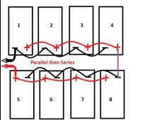
Read the first 4 posts of this thread to understand the issues. There are better ways to wire your batteries (not terrible, i've seen lot worse!)and wired like image obtained from the web , all is working fine but im not comfortable with it , is there a better way ?

Calculation of parallel string battery currents
Hi, everybody! I'm a retired EE. I didn't want my EE skills to fade away after retirment, so I exercise them when I can. Whenever I see a non-trivial circuit analysis problem on one of various forums I frequent, I challenge myself to solve it. Recently I watched Will's video about current...
 diysolarforum.com
What battery type? Only thing I would do is maybe add a midpoint voltage meter.
I have nae idea what that means
")
im am just playing with car batteries , lead acid
Thankyou mr Sandals appreciate time taken to reply
I have had a quick look and its gonna take me a long time to
fully understand. I am currently spoonfeeding myself with easy to read
images from the web , understading fully is good but its also very time
consuming a brain numbing
anybody any thoughts on rewiring like this attached image
I have had a quick look and its gonna take me a long time to
fully understand. I am currently spoonfeeding myself with easy to read
images from the web , understading fully is good but its also very time
consuming a brain numbing
anybody any thoughts on rewiring like this attached image
Attachments
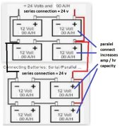
I use method 3, it's very easy done ,

Last edited:
Thankyou mr Sandals appreciate time taken to reply
I have had a quick look and its gonna take me a long time to
fully understand. I am currently spoonfeeding myself with easy to read
images from the web , understading fully is good but its also very time
consuming a brain numbing
anybody any thoughts on rewiring like this attached image
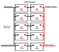
The goal is to load / charge all batteries as equally as possible ,
The trouble with that diagram is the load isn't spread evenly at all ... the two batteries at the top are going to have to do more than their fair share of the work and so degrade faster....
each pair of batteries down will do less and less
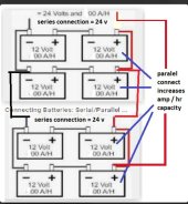
This would be a lot better (simple fix):

Drawing/charging the bank diagonally spreads the work across all more batteries evenly
The original parallel-series is likely marginally better with 24V and lead acid and no balancer. It is good to monitor the voltage though between the two endpoints and midpoint (the two 12V readings). The logic is the charger is only controlling the 24V nominal voltage, so you only have one indeterminant point within your control.
When you go series-parallel then the four midpoints are all indeterminant.
The difference is only marginal though since you have 24 indeterminant points within the 8 batteries themselves.
When you go series-parallel then the four midpoints are all indeterminant.
The difference is only marginal though since you have 24 indeterminant points within the 8 batteries themselves.
I use method 3, it's very easy done ,
Thankyou , the smart guage link a lot easier for me to understand , although i need to put some thought into it for 24v once i have decided which method i prefer
it was worth reading just for this comment , which have been wondering
"And finally, finally, we keep getting asked where the chargers should be connected to. We didn't address this question because it seemed so blatantly obvious where they should be connected that it never occurred to us that anyone might be unsure. The chargers should always be connected to the same points as the loads. Without exception."
The goal is to load / charge all batteries as equally as possible ,
The trouble with that diagram is the load isn't spread evenly at all ... the two batteries at the top are going to have to do more than their fair share of the work and so degrade faster....
each pair of batteries down will do less and less
This would be a lot better (simple fix):
View attachment 149331
Drawing/charging the bank diagonally spreads the work across all more batteries evenly
The blue lines , what do they represent ? , might seem obvious to you , but just confusing me
Oh ! I think they're just annotations, like arrows for that labelThe blue lines , what do they represent ? , might seem obvious to you , but just confusing me
Definitely not cables , ignore them
Thankyou , the smart guage link a lot easier for me to understand , although i need to put some thought into it for 24v once i have decided which method i prefer
it was worth reading just for this comment , which have been wondering
"And finally, finally, we keep getting asked where the chargers should be connected to. We didn't address this question because it seemed so blatantly obvious where they should be connected that it never occurred to us that anyone might be unsure. The chargers should always be connected to the same points as the loads. Without exception."
Someone on here sent me that link when I was first starting out , always found it very helpful
Oh ! I think they're just annotations, like arrows for that label
Definitely not cables , ignore them
OK cool , i thought so but just wanted it confirmed
Ok to move to that pack is quick and easy, easy install of 3 short cables
Interesting that the load/Charge + has moved to bottom right post
I shall experiment with that first, i think my preferred method is "method 3"
easy to understand and easy to add new batteries in due course , but that will
take more work and cable to change
Yes it's a good bit of cabling to get method 3 sorted but ones it's done it's done
Try cut all cables the same length - again aiming to equally drain the batteries
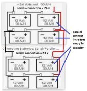
Here is method 3 for 24v:

Ok just checked the voltages of each battery , the left bank were all lower
so i would say that means the original way i wired , very first image , in my very first
post in this thread was , "operable but poor "
I have just rewired and using bottom right post for charge / draw , lets see how it goes
i shall report back in due course
so i would say that means the original way i wired , very first image , in my very first
post in this thread was , "operable but poor "
I have just rewired and using bottom right post for charge / draw , lets see how it goes
i shall report back in due course
Ok just checked the voltages of each battery , the left bank were all lower
so i would say that means the original way i wired , very first image , in my very first
post in this thread was , "operable but poor "
I have just rewired and using bottom right post for charge / draw , lets see how it goes
i shall report back in due course
Brilliant , if they are unbalanced it might pay to disconnect all batteries, individually charge each one for 12/24hrs on a little 12v charger , and then after that reconnect
This will make sure all batteries are at the same level - completely full
The reason we draw on the system diagonally is we are trying to load each battery equally ,
littleharbor2
Solar Addict
No good. Uneven charging and uneven load draw but at other end of bank. Don't go there. Even length cables and bus bar is the way to go. Plus you have a convenient power tap point with bus bars and can remove/replace/add batteries easily without shutting down the system.
In the same vain , im not saying good or bad , but just read this .................
"The battery cables should be of the same length and same size and as straight as possible. Always connect loads and charging sources to positive and negative terminals at opposite ends of the battery bank, otherwise the first battery will do all the work and the bank will become unbalanced and fail quickly.
"The battery cables should be of the same length and same size and as straight as possible. Always connect loads and charging sources to positive and negative terminals at opposite ends of the battery bank, otherwise the first battery will do all the work and the bank will become unbalanced and fail quickly.