diy solar

diy solar

Battery at 12.3v under load. When load removed its 12.6v this isnt discharged?

I notice you've got multiple wires coming in to the negative posts on your batteries. To get an accurate measurement of current going in and out, you want all the negatives connected at the shunt. You should also move the positive lead to the opposite battery in the string.
I have 2 charge controllers.
 
I notice you've got multiple wires coming in to the negative posts on your batteries. To get an accurate measurement of current going in and out, you want all the negatives connected at the shunt. You should also move the positive lead to the opposite battery in the string.
My shunt feeds the inverter so I can see the load and battery voltage. That's all I really use it for. I look at my 2 epever 40amp charge controllers to see what kind of production I have.
 
I notice you've got multiple wires coming in to the negative posts on your batteries. To get an accurate measurement of current going in and out, you want all the negatives connected at the shunt. You should also move the positive lead to the opposite battery in the string.
And a Class T fuse would be nice.
 
And a Class T fuse would be nice.
So honestly I don't know what that exactly is. Yeah I'm new to this. I would prefer a breaker. Next time I go to santan solar maybe. What all do I need?
Cut off switches between the solar arrays? And between the cc and batteries a breaker?
And inverter and batteries?
I dont run anything while I'm not here. I've been using deans hobby connectors on my pv wires two some 12ga wire for less strain on the epever charge controllers.
I started witha 100w hf panel back in May this year. Lol ? so forgive me. I'm trying to learn as much as possible. Reading. Asking dumb questions, watching videos. Searching internet.
Buying stuff, testing it, buying more stuff.
I've been through 4 different cc before I got these epever 40amp tracer 4210an ones. Tried 2 240w santan used panels at first and now I'm up to 8. Might get 2 more . The ground mount sucks. Wish I could adjust them more
 
(Proper) circuit breakers are always good. Especially for maintenance.
The concept of drawing from opposite poles... just think about it.
While imbalances are pretty much unavoidable, it doesn't mean they should be... encouraged ;·)
-
 
So honestly I don't know what that exactly is. Yeah I'm new to this. I would prefer a breaker. Next time I go to santan solar maybe. What all do I need?
Cut off switches between the solar arrays? And between the cc and batteries a breaker?
And inverter and batteries?
I dont run anything while I'm not here. I've been using deans hobby connectors on my pv wires two some 12ga wire for less strain on the epever charge controllers.
I started witha 100w hf panel back in May this year. Lol ? so forgive me. I'm trying to learn as much as possible. Reading. Asking dumb questions, watching videos. Searching internet.
Buying stuff, testing it, buying more stuff.
I've been through 4 different cc before I got these epever 40amp tracer 4210an ones. Tried 2 240w santan used panels at first and now I'm up to 8. Might get 2 more . The ground mount sucks. Wish I could adjust them more
It's fun to watch someone taking off on thier solar journey! You're doing fine, we just don't want you to burn your house down. I still have plenty to learn myself but I do have a decent grasp of the big parts of the electrical stuff at least.

Roughly speaking.... a Class T fuse is capable of safely and reliably opening while taking the full punch from the battery when there is dead short in your system. Some types of fuses may fail in such a way that they don't open so the problem continues until the wires melt in two or the energy in the battery is depleted.

Please take a few minutes and do some research on AIC.

Here's one thread I found that talks about it. https://diysolarforum.com/threads/class-t-vs-anl-fuse.13913/
I've seen issues with cheap fuse holders. Should I just use circuit breakers?
 
It's not that simple unfortunately. Read that link I sent.
6 pages. I've read some of it.
I'm sure what I have here is completely unsafe. I dont even know where to start now. I'm a automotive mechanic with formal training and a amateur radio extra class license holder. And a bit crude and redneck. I'm not sure what I need to do next.
I like " keep it simple stupid." That's my moto as a sober alcoholic.
I'm good at breaking stuff
 
Well, you should really move the positive lead to the opposite battery in the string, though ;·)
-
Ok I moved it. Now what about the 2 sets of cc wires? Same or opposite. Originally I thought each on goes to a different battery might help balance things. But I see that being a problem now since the biggest battery is not fed directly. 20220704_154214.jpg
 
6 pages. I've read some of it.
I'm sure what I have here is completely unsafe. I dont even know where to start now. I'm a automotive mechanic with formal training

I don't normally post up what I have for a background, but for you, I'll make an exception.

The first lesson you need to learn as an automotive mechanic, which I am not, I am an automotive master technician of over 35 years of shop ownership; is when constructing anything, whether it is an electrical circuit, an exhaust system, building a house, virtually anything, you should make it look like you knew what you were doing. If you don't know what you're doing, then you should educate yourself on the proper methodology and practice.

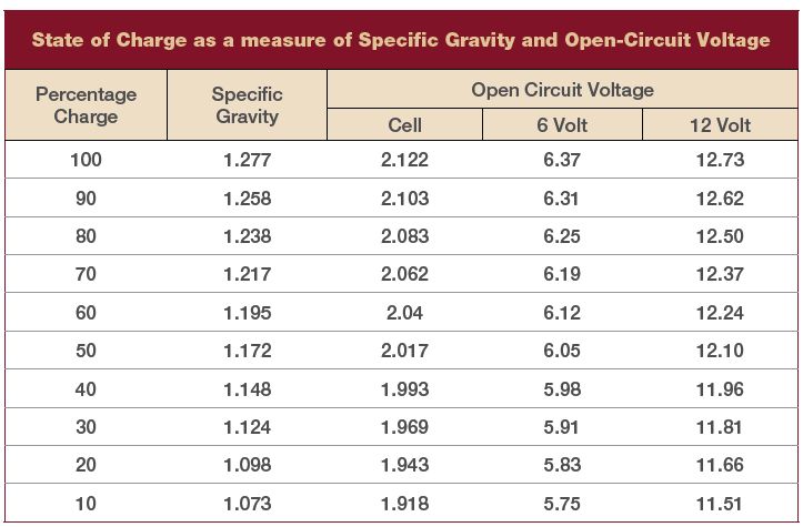
What I'm trying to understand is how anyone could go thru formal training as an automotive tech in this day and age and not know what load testing of a lead acid battery truly is and how the results should be interpreted. Then we move on to voltage drop testing of a circuit, how it should be performed and determining resistance in a circuit.

If you don't know, then get educated. If you want to hang out with real professionals in the industry, then I suggest you step up to the real university of automotive repair knowledge online, known as IATN, International Automotive Technicians Network. You can join for free with a basic membership as long as you qualify. http://www.iatn.net/

I've been a sponsoring member there since 2004. The best in the industry hung out there, there was some that left or passed away over the years but the knowledge there is top notch. Step up your game, become a true professional. Redneck crap in the days of increasing technology, complexity and systems integration is no way to go thru life, much less a career. And be prepared to have a thick skin, you will have members call you out if you try to con your way thru, sharp bunch but you will learn from mistakes too.

The reason I posted this, and no, my complete business model is not entirely as an automotive technician, is because I see what I consider very substandard methods used to build an electrical circuit in your photos. While you believe if it "works", it's good enough, however over the last 40 plus years of turning wrenches and repairing electrical circuits and components, I can tell you the workmanship you have with your current standards is destined for failure and quite likely catastrophic.


and a amateur radio extra class license holder. And a bit crude and redneck. I'm not sure what I need to do next.
I like " keep it simple stupid." That's my moto as a sober alcoholic.
I'm good at breaking stuff
Instead of being good at breaking stuff, you should strive to build the best "product" you can. It takes not only an investment of your time to gain knowledge but also to put it into practice.
 
SOC is usually measured under no load.

View attachment 100994
BCI defines RC (reserve capacity) in minutes by discharging at a constant 25 amp load to 10.5 volts. I know what the chart says but this is a loaded battery chart.

No load resting for 24 hours is closer to this:

voltchart2.gif


The OP is discharging at 50 amps not 25 so the voltage will sag more than the first graph and recover more when the load is released.
Never going to be an exact measurement using voltage alone. With use over time better estimates can be made.

Here is another chart that conflicts with both the above:

post-16-0-81274800-1406914693.jpg


Good luck ;)
 
That chart is useless without temp compensation.

12.73V with surface charge removed, that would be a fairly new battery without any sulfation.......
 
Back
Top