You need a battery selector - you can choose between battery banks with it -
basically this is what I was building was one that worked off your existing control and some contactors to do the work automatically, with a safety feature to prevent both from being connected at once.
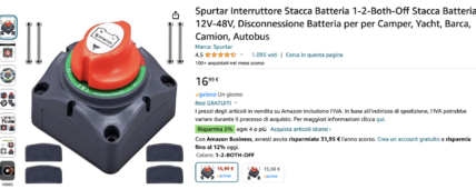
Technically you can just use a generic battery disconnect in the negative line of each battery bank
Turn off inverter
turn off AGM
turn on LFP
turn on inverter
OR
turn off inverter
turn off LFP
turn on AGM
turn on inverter
It won't be automated and it won't have any safety interlock to prevent you from turning on both at once. Not terribly safe in the long run because all it would take is once of turning them on while the AGM is drained and the LFP is full or vs versa and damage would happen to one of them.
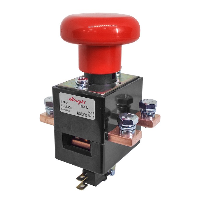
You could get two of these and put them in a box with an interlock to prevent them from both being on
Or any other set of DC rated breakers and an interlock kit (basically a piece of sheet metal mounted in such a way that when you switch the handle of one the other is tripped and vs versa
Look up generator interlock and you will see what I mean. The critical part is to get breakers that are rated for DC and are dual pole so you connect and disconnect both positive and negative at once.