diy solar

diy solar

Battery Cable Layout/Design ~ Seems like a Lot of Connections

MrM1

I'm Here, But I'm Not All There
Joined
Mar 1, 2021
Messages
2,422
Location
N. Central FL
So I'm Sitting here today laying out the cable design from my battery banks to the Inverter. Putting it all on paper helps me visualized how I will set it all up, and how many lugs I will need, what sizes, and what size cables, etc.

But Boy! ... This seems like a boat load of connections. Is this Typical? Is this going to be a problem for resistance etc making up all these little short cable? I have a 10 ton (?) Hydraulic press crimper for making the cold welds to the lugs that does a good joy and I enjoy using. So I am not concerned about that, but is this many connections typical?

Note: the #7 wire is out of my control as it is fixed to the BMS but is double and is only 5 inches on each side. The 2/0 will be about 12 inches long to the fuse. Everything else will be 4/0

What Could I do differently?
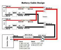
Battery Cable Layout Design.JPG
 
You could eliminate a few by bolting the shunt directly to the bussbar, and rounte negative around the switch…
 
You could eliminate a few by bolting the shunt directly to the bussbar, and rounte negative around the switch…
Yeah I am seeing that. Great Idea.

So having that many connections is not a problem and not uncommon.
 
Yeah I am seeing that. Great Idea.

So having that many connections is not a problem and not uncommon.
Well, every connection is a place for a mistake, and requires severe anal cleaning and torque
 
I see your neg coming from both BMS, to a "stud" and then to what looks like a terminal block. Have you considered moving the terminal block close enough to the BMS so the BMS leads will be right to the terminal block? That would remove a connection point. Or make your BMS wires longer and run them to the terminal block.
 
I see your neg coming from both BMS, to a "stud" and then to what looks like a terminal block. Have you considered moving the terminal block close enough to the BMS so the BMS leads will be right to the terminal block? That would remove a connection point. Or make your BMS wires longer and run them to the terminal block.
How would you lengthen the BMS wire? It does into a black case on the HelTec BMS units. Idea have to take that apart and solder in new wire. Doable, but soldering is my weak point. Is there some other way to lengthen ?
 
How would you lengthen the BMS wire? It does into a black case on the HelTec BMS units. Idea have to take that apart and solder in new wire. Doable, but soldering is my weak point. Is there some other way to lengthen ?
I was not thinking of that type BMS....sorry. The type I use, you can replace the wires fairly easily.
 
Something seems off, you have 4/0 awg and 7 awg in the same circuit.
What ampacity is the bms rated for?
How far apart are the components?
 
Something seems off, you have 4/0 awg and 7 awg in the same circuit.
What ampacity is the bms rated for?
How far apart are the components?


The Heltecs BMS are rated for 200a each. I agree it is off, but the Heltecs come with #7 wire x2 on both sides (B and C). The run of the double #7 will be less than 8 inches total (4" on each side of the BMS) and the run of the postive 2/0 from the battery to the fuse will be the same.

That being said I could probably then use 2/0 all the way thru, but I already have the 400amp fuses and switch, and the inverter is rated for that much. Thing about it is, as long as one of the 2 BMS units does not shut down unknowingly, there will never be more than 200 amps coming from each string to the busbars. But this is why I may end up going with yet a 3rd string of batteries, for more capacity AND to add a 3rd BMS for redundency. The likelihood of 2 out of 3 going down gets pretty slim.

But I agree, it seems and odd limitation of the BMS and not sure why they use double #7 on a BMS rated for 200 amps continuous.
 
Darn it @smoothJoey ... just realized I probably should have gotten 200 amp T-Fuses, That would have created a fail safe in case one bms did go down without us knowing and would have allowed for 2/0 to the busbars. Might just return them.
 
That could be because the soldering pads are smaller on the BMS. Also could the silicon wire have a higher current rating?
I need to look.

But does it make sense to downgrade my T-Fuses to 200amp and run 2/0 to the busbars (except for the double #7 that I cannot change). I think that would add a fail safe in case one BMS where to shut one bank down. If only running on one bank and the inverter tried to pull more than 200amps it would blow the fuse, shut down the 2nd bms and shut down the system
 
The Heltecs BMS are rated for 200a each. I agree it is off, but the Heltecs come with #7 wire x2 on both sides (B and C). The run of the double #7 will be less than 8 inches total (4" on each side of the BMS) and the run of the postive 2/0 from the battery to the fuse will be the same.

2x 7 awg is eqivalent to 4 awg.
Also its probably high temp silicone insulated wire.
Each circuit is limited by its weakest link.
In this case its the bms.

That being said I could probably then use 2/0 all the way thru, but I already have the 400amp fuses and switch, and the inverter is rated for that much. Thing about it is, as long as one of the 2 BMS units does not shut down unknowingly, there will never be more than 200 amps coming from each string to the busbars. But this is why I may end up going with yet a 3rd string of batteries, for more capacity AND to add a 3rd BMS for redundency. The likelihood of 2 out of 3 going down gets pretty slim.

But I agree, it seems and odd limitation of the BMS and not sure why they use double #7 on a BMS rated for 200 amps continuous

This makes more sense notice the fuse on the inverter leg.
Because of the change in wire length it needs a fuse of its own.
That one doesn't need to be class-t though.
The BMS has over-current protection so I say let it look after itself.

I don't know the distances so I can't address the voltage drop.
Code:
dc {
    pos {
        2/0awg|<->300A_fuse<->battery_0.pos
        2/0awg|<->300A_fuse<->battery_1.pos
        4/0awg|<->400A_fuse<->400A_disconnect<->12KW_inverter.pos
    }
    neg {
        2/0awg|<->bms<->battery_0.neg
        2/0awg|<->bms<->battery_1.neg
        4/0awg|<->shunt<->12KW_inverter.neg
    }
}
 
Last edited:
2x 7 awg is eqivalent to 5 awg.
Also its probably high temp silicone insulated wire.
Each circuit is limited by its weakest link.
In this case its the bms.


This makes more sense notice the fuse on the inverter leg.
Because of the change in wire length it needs a fuse of its own.
That one doesn't need to be class-t though.
The BMS has over-current protection so I say let it look after itself.

I don't know the distances so I can't address the voltage drop.
Code:
dc {
    pos {
        2/0awg|<->300A_fuse<->battery_0.pos
        2/0awg|<->300A_fuse<->battery_1.pos
        4/0awg|<->400A_disconnect<->12KW_inverter.pos
    }
    neg {
        2/0awg|<->bms<->battery_0.neg
        2/0awg|<->bms<->battery_1.neg
        4/0awg|<->shunt<->12KW_inverter.neg
    }
}
So are you saying down grade the two 400amp fuses to 300amp but ALSO put a single 400amp fuse on the inverter side of the busbars?
 
So are you saying down grade the two 400amp fuses to 200amp but ALSO put a single 400amp fuse on the inverter side of the busbars?
I showed 300 amp class t fuses but yes.
Technically you could omit the fuse on the inverter circuit.
 
Here is a table that I use
Code:
for pure copper wire with insulation rated to 105 Celcius

ring terminals or ferrules
  16 -  up to 4 amps service current, 5 amp fuse
  14 -  up to 12 amps service current, 15 amp fuse
  12 -  up to 16 amps service current, 20 amp fuse
  10 -  up to 24 amps service current, 30 amp fuse

lugs or ferrules
   8 - up to 40 amps service current, 50 amp fuse
   6 - up to 80 amps service current, 100 amp fuse
   4 - up to 120 amps service current, 150 amp fuse
   2 - up to 160 amps service current, 200 amp fuse

lugs
   0 - up to 200 amps service current, 250 amp fuse
  00 - up to 240 amps service current, 300 amp fuse
0000 - up to 320 amps service current, 400 amp fuse
 
Back
Top