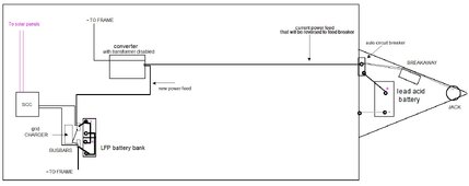
My current camper 12 Volt system consists of a lead acid battery on the tongue, and a WFCO converter inside. The wire from the battery to the converter is AWG 10 and also carries current from the tow vehicle when connected.
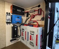
My new power source will be a 440 AH 12 Volt LFP bank inside the camper.
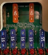
I wish to do away with the tongue battery, and repurpose the main charging/supply wire to feed the power jack and break away switch, by removing that #10 wire that currently feeds the fuse panel, and using it as a branch circuit. It is currently protected by a 40 Amp fuse in the panel, but will be reduced to a 30 Amp.
The new battery bank will have new 50 Amp wire that feeds the converter as I have a 40 Amp charger. The converter will then need a 50 Amp fuse.
Doing this will then feed those tongue mounted devices from the fuse box. However, the incoming power feed from the tow vehicle also connects to the auto circuit breaker on the tongue.
Am I safe to back feed that incoming power to my new LFP battery bank through the old wire (which is rated for 30 Amps) to the fuse panel, or do I need to run the tow vehicle charging wire to my battery bank bus bar? I am aware that the voltage from the tow vehicle isn’t going to do much for my higher voltage LFPs. I may at some point add a DC-DC charger, but I believe for it to be effective, I would need to run much heavier cable from the tow vehicle battery all the way back to my new battery bank?
I also will be adding solar, so it is possible that the SCC could be putting out up to 80 Amps at the same time the charger (shore power) is running.
Am I correct in believing I need to up my wire capacity to account for that, or make sure they both never run at the same time?
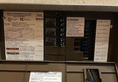
Next is the converter. It is a WFCO WF-8955PEC, which is rated at 55 Amps. I plan to disconnect the converter transformer, so that all power is fed from my battery bank, even when connected to shore power.
Our camping consists of off grid for multiple days until the battery bank, assisted by solar, is mostly depleted, then connecting to grid for a night to recharge.
I could switch out the circuit board so it would produce the higher charging voltage needed, but it still isn’t a very good charger, compared to my stand alone, and is another expense that seems unnecessary?
The converter at least at first glance appears defective, as it is sometimes putting out 13.68 Volts and other times putting out 17.47 Volts, which may be why it was regularly cooking the previous owner’s lead acid battery on the tongue.
My new power source will be a 440 AH 12 Volt LFP bank inside the camper.
I wish to do away with the tongue battery, and repurpose the main charging/supply wire to feed the power jack and break away switch, by removing that #10 wire that currently feeds the fuse panel, and using it as a branch circuit. It is currently protected by a 40 Amp fuse in the panel, but will be reduced to a 30 Amp.
The new battery bank will have new 50 Amp wire that feeds the converter as I have a 40 Amp charger. The converter will then need a 50 Amp fuse.
Doing this will then feed those tongue mounted devices from the fuse box. However, the incoming power feed from the tow vehicle also connects to the auto circuit breaker on the tongue.
Am I safe to back feed that incoming power to my new LFP battery bank through the old wire (which is rated for 30 Amps) to the fuse panel, or do I need to run the tow vehicle charging wire to my battery bank bus bar? I am aware that the voltage from the tow vehicle isn’t going to do much for my higher voltage LFPs. I may at some point add a DC-DC charger, but I believe for it to be effective, I would need to run much heavier cable from the tow vehicle battery all the way back to my new battery bank?
I also will be adding solar, so it is possible that the SCC could be putting out up to 80 Amps at the same time the charger (shore power) is running.
Am I correct in believing I need to up my wire capacity to account for that, or make sure they both never run at the same time?
Next is the converter. It is a WFCO WF-8955PEC, which is rated at 55 Amps. I plan to disconnect the converter transformer, so that all power is fed from my battery bank, even when connected to shore power.
Our camping consists of off grid for multiple days until the battery bank, assisted by solar, is mostly depleted, then connecting to grid for a night to recharge.
I could switch out the circuit board so it would produce the higher charging voltage needed, but it still isn’t a very good charger, compared to my stand alone, and is another expense that seems unnecessary?
The converter at least at first glance appears defective, as it is sometimes putting out 13.68 Volts and other times putting out 17.47 Volts, which may be why it was regularly cooking the previous owner’s lead acid battery on the tongue.