diy solar

diy solar

Battery Current MPPT vs Shunt in a Victron System

Sailing-solar

New Member
Joined
Oct 12, 2023
Messages
2
Location
North Carolina
I recently had a BMV-712 installed along with some solar panels and a Victron MPPT. I wanted to check with folks more knowledgeable than me to see if the output I’m getting that’s delivered to the batteries is normal.

I understand that the shunt current reading is net of charge and loads. If I turn off all loads there seems to be a significant difference in the current shown from the MPPT vs the shunt.

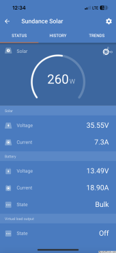
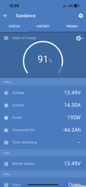
For example today solar is sending 18.9A to the batteries while the shunt shows net current of 14.3A.The parasitic draw tends to be about 0.5A so the discrepancy would be about 4A.

I’m charging a 480Ah Victron AGM house bank and have a Cyrix combiner to maintain one AGM start battery. The start battery is full but should be getting a float charge so that should account for a small amount of the discrepancy correct?

It seems I’m losing about 15 to 20% somehow in the process. Am I correct that the loss seems excessive?
 

Attachments

  • IMG_5023.png
    IMG_5023.png
    105.3 KB · Views: 3
  • IMG_5024.png
    IMG_5024.png
    113.7 KB · Views: 3
The MPPT is sending 18.9A to the DC bus, not the battery. If you have an inverter that is powered on, but has no loads on it, it still has idle load consumption that could easily be at least an amp or two. You could easily have another amp or two going to the AGM through the Cyrix.

The easy answer is to get a clamp DC ammeter and verify all readings. You'll see exactly where the current is going.

Might also be worth conducting a zero current calibration on the shunt.
 
Last edited:
Thanks for your insight. The screen shots are from when all switched loads were turned off, including the inverter. You’re spot on that on standby the inverter draws just under an amp.

When loads are off there’s a 0.5 draw on the battery which I deducted when computing the 4amp discrepancy.

I will purchase clamp meter that can read DC current and see how much is going to the starter battery per your suggestion.

Am I correct that absent loads the output to the DC bus should be within a few % of what the shunt shows for current?

If you simply had a battery attached to a shunt and an MPPT with nothing else, I would expect the two current readings to be very close - say 1-2%-ish.

Something worth considering is to set them up in a VE.Smart network via bluetooth. The shunt will pass both voltage and current data to the MPPT. The MPPT will use that current data for tail current if enabled. It also passes the open circuit voltage to the MPPT, so it doesn't make decisions based on the current influence voltage it measures (higher), but the shunt reported voltage, which is not influenced by current in either direction. If you have a temperature sensor with the BMV, it will also pass temperature data to the MPPT to be used for temperature compensation for lead acid, or low temp charge protection for Lithium.
 
Am I correct that the loss seems excessive?
To be sure the Cyrix is not the problem you need to disconnect from the system. The Cyrix is a combiner not a charger so the battery will be taking power.
The more probable is that one of the battery bank negatives is bypassing the shunt.
 
Back
Top