amazinghank
New Member
- Joined
- Mar 24, 2021
- Messages
- 26
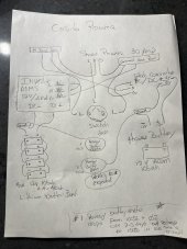
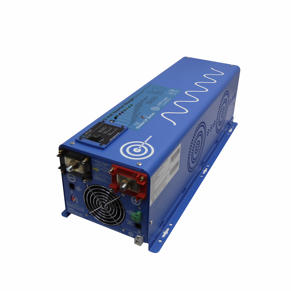
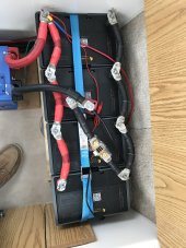
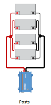
I have a Casita trailer with a new 105ah AGM House battery plus 4-105ah Lithium Batteries in a bank tied to a 4000 watt AIMS Pure Sinewave Inverter & Charger.
A year ago I installed a Renogy Battery monitor on just the Lithium bank (with a shunt) and everything was fine & worked as expected.
The original converter is still used to charge the house battery and run all the A/C breakers & DC equipment.
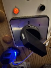
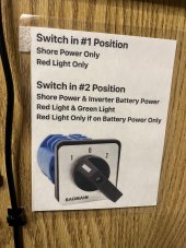
The two systems are separated by a switch that only switches the positive wires for either the shore power or the inventor power. The grounds are all joined (not switched) and have not had an issue until I recently added a 2nd Renogy Battery monitor for the AGM house battery and that seems to work fine, except that now the 1st monitor (lithium bank) showed consumption (-5.6 amps) and the % drops steady so that the 100% is down to 20% or less in 2-3 days ( with the lithium bank switched off) when I switch back on it goes back to 100% very quickly, as though the batteries aren’t really depleted.
Are the 2 shunts confusing the meters because the negative wire are common? I’m confused
Do I need to run negative wires through a switch to separate?
A year ago I installed a Renogy Battery monitor on just the Lithium bank (with a shunt) and everything was fine & worked as expected.
The original converter is still used to charge the house battery and run all the A/C breakers & DC equipment.
The two systems are separated by a switch that only switches the positive wires for either the shore power or the inventor power. The grounds are all joined (not switched) and have not had an issue until I recently added a 2nd Renogy Battery monitor for the AGM house battery and that seems to work fine, except that now the 1st monitor (lithium bank) showed consumption (-5.6 amps) and the % drops steady so that the 100% is down to 20% or less in 2-3 days ( with the lithium bank switched off) when I switch back on it goes back to 100% very quickly, as though the batteries aren’t really depleted.
Are the 2 shunts confusing the meters because the negative wire are common? I’m confused
Do I need to run negative wires through a switch to separate?