diy solar

diy solar

BMS shutting off system power when over voltage?

Pincones

New Member
Joined
Oct 31, 2020
Messages
53
Another question about our new setup! We're loving the switch to LFP. Now that spring is near, we're seeing bright, beautiful days of full sun after 2-3 months of low light. So for the first time, our battery is really getting power-charged.

We've recently been running into a problem when the sun hits the panels full-blast, the battery zooms up to max voltage and the BMS starts cutting power on and off to the whole system. That doesn't seem right to me. Surely it should let us keep using the power from the battery, then continue charging it once the voltage drops?

My BMS is is a 200amp in/400amp out BMS, advertized as Daly but has no branding on it. It's big and beefy and looks well built. No read-out or data access from it though.

When the bank hits 14.4, it's not simply that the power shuts off. The BMS makes clicking sounds and power gets cut on and off rapidly over and over. The inverter beeps spastically because it's 12v power supply is being cut on and off. The house power cuts in and out. After some rapid, repeated clicking and beeping from the system, the BMS will 'officially' cut off charge to the battery and the power goes out. The voltage must drop down to 12.2/12.1 before the BMS clicks again and the battery starts charging again and releases power back into the system. The BMS will let it drop as low as 11.9, but generally seems to allow charging again at 12.2.

We've taken to either shutting the system down in full sun and using no electricity, thus allowing the BMS to just shut off and stay off, OR splurging as much power as we can and creating a really heavy draw so the bank doesn't max out its voltage.
The latter works very well. Today we're running 3 freezers, charging some power tool batteries, running the computer monitor on it's brightest setting, and have turned every last light on in the house. Aside from plugging in a shopvac or table saw, that's as much as we can pull. With all of our stuff plugged in and pulling max power, the system is not reaching 14.4v and is not shutting off. It hovers between 13.9-14.2 and everything works happily.

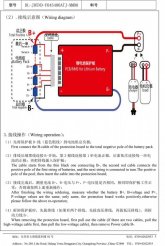
As per the shunt's wiring diagram, I have the BATTERY- wired to B- on the BMS, then the P- on the BMS wired to the shunt, then the shunt wired to the system negative. The BATTERY+ is wired straight into the system positive. I also have a battery monitor hooked to the BATTERY+ and the BATTERY-, as well as on each side of the shunt. When the BMS kicks power on and off, the battery monitor's power hiccups as well. It doesn't shut off for an extended period, but the screen flashes on and off and it updates rapidly with the voltage jumping around between 12.0 to 14.4.
The shunt and the monitor came together and I wired them per the instructions. I might take the shunt out and see if that's causing a problem, but it doesn't seem like that's the problem to me.

Anyway... If specs help;
Array: 750 watt
CC: 60amp programmed for LFP
BMS: 200/400amp 4s 12v
Bank: 4s 12v 280ah LFP
Shunt: 100amp
Inverter: 2000/4000 watt pure sine
Average power draw at any time: 200 - 800 watts
Whole system is grounded to earth.
 
Now, I need to have you clarify, this is a "Dumb" BMS which means no Bluetooth / User Interface and not programmable/adjustable? Is that correct ?

With a Dumb BMS you have FEW OPTIONS, I will give you the "Trick" and some will argue against it but that is mostly because they simply do not understand or are running with poor assumptions. You say, you can operate without issues until the Battery Pack goes past 14.2V. " It hovers between 13.9-14.2 and everything works happily". 14.2V is 3.55V per cell which is 100% FULL. In fact, if you can charge above 3.450V per cell you are above 95% as LFP primary voltage curve is 3.000-3.450 (12.0V-13.8V). * Even IF you charge LFP cells to 3.650V each and saturate them till they take less than 1A charge rate, within 4 hours they will settle to about 3.500 and 12 hours to 3.450 +/- 0.050 which is quite normal.

You can set your Max Charge Voltage 14.0V on your SCC / Charger systems.
Set FLOAT Voltage to 13.6V.
Set Equalize to OFF !!!
Set Bulk Charge to a Maximum of 15 minutes.
End Amps (typically used by Bulk) is 14A for a 12V/280 Pack.

*FLOAT* Is not "needed" by LFP batteries BUT if you are running as you do, with solar charging ongoing while also using the inverter and drawing power, float if your buddy, pal & friend.
- Bulk Charging will flip to float as soon as it hits Full Voltage threshold which is 14.2V (when the BMS kicks off). By setting the Charge Voltage Max to 14.0 you will not hit HVD and are still 100% Full.
- With float pushing whatever it needs as per demand from the Inverter, it can service the "needs" to continue running without pushing excess voltage to the battery. If the demand all of a sudden exceeds what Float can provide, the batteries will get called upon to fill in the balance.
- Once the load is over and batts slightly discharged the SCC should kick back into Bulk to top off at 14.0V before flipping back to float mode.

Many people get the Notion that once the battery is full the solar panels ought to be shutoff. Not the case and a bit "Chicken Little" because Float is there for just such cases. Batteries, regardless of chemistry do hit Full Charge and cannot take more, so the power has to go somewhere, might as well be used to service ongoing power drain. In some instances, excess power can also go to a Dump Load like a Hot Water heater (tank) or something but that is another creature altogether.

There is more info in my Luyuan Tech Basic Lifepo4 Guide

Hope it helps, Good Luck
 
Yep it's a dumb BMS. Haha! Why, though, would it shut off system power at full voltage?! That seems ridiculous, but maybe there's something I don't understand there.

The reprogramming suggestion seems like it makes sense. I can certainly update the CC to new specs.

And yes, as long as we stay below 14.2v everything runs normally. We don't jump over 14.2v unless the array is getting a full blast of sunshine. We just upgraded to LFP in November, so this is our first "sunny season" with the LFP. This is a new experience. We will be adding 8 more cells, for x3 280ah batteries. We were going to do this in January and read a helpful thread here about avoiding ordering LFP's just before, during, and just after Chinese New Year. So at the end of this month we'll be expanding the bank, hopefully that also helps balance the equation since we're bringing in way more power than we need/use.
 
Well, actually, it is not a matter of shutting because of being at full voltage, it is protection from overvoltage. One of the primary functions of a BMS is to protect each cell in the pack from Over/Under voltage conditions, as well as battery Temperature being out of limits. If any cell goes above or below the programmed settings the BMS will cut off to prevent the cell from being damaged.

With the usual commodity cells people are buying here, they are Voltage Matched but not properly matched and batched. There's been a ton of talk on this, I won't get into it again. sorry. It is not uncommon to have a lazy cell or a "runner", either of which could reach one of the cutoff points before the rest of the cells, these will be the limiters of the battery pack overall.

When putting packs in parallel, you have to be a tad finicky. Same grade of cables & lugs, same lengths from the battery to busbars, quality busbars & fuses. Things get a bit tricky with more packs because each pack has to be capable of being the "Last Man Standing" if the others cutoff during charge/discharge. Using 280AH cells, you will be able to charge at a Max of 140A and draw a Max of 280A (3360W @ 12V) to fit that. BUT with packs in a "properly" balanced parallel setup, they divide the load & charge quite evenly, until one or more packs drop connection.

So again the trick is to keep the voltages for Charging & Discharging within the top & bottom cutoff points of the BMS or the specified range you program if using a smart BMS. Voltage Readings between the batteries, SCC, Inverter/Charger "must" be correct and calibrated for voltage drops etc through the wiring & connections. While a bit off with Lead Batteries is OK, any Lithium system regardless of chemistry "needs" accuracy. If the voltage reads as 14.00 at the battery terminals, it may be 13.95 @ the SCC and 13.90 @ the Inverter Charger terminals and you know that at 14.20 the battery packs will drop charging you will want to cutoff charging at 14.10 and not at 14.15V (from the SCC) or 14.20V (from Charger). If possible and you can afford it, it's better to spend a little extra and better quality cells which are at least factory Matched & Batched in lots rather than from vendors who are using various brokers.

nb: finisky, properly - elude to being a bit anal-retentive about it. ?

BTW: Material Costs for manufacturers are going up due to supply & demand, so that means costs for cells will be increasing shortly. Don't hesitate too long, remember it takes ages (point of view) for stuff to get to destination.

EDIT -
As you increase the battery capacity, so will the need for solar panels & charge controller to handle charging the extra.
It takes me 8 kWh of Generation to charge 50% of my current 910AH Battery Bank. give or take a bit. Because I am also running my inverter & loads at the same time.
 
Last edited:
Good to know about the demands for consistency. We'll make sure to use the same bars for everything. Your personal thoughts on letting 1 BMS share packs vs. getting a BMS for each pack?
 
That sounds like crappy BMS to me. My Overkill Solar BMS will cut off charging, while discharge is still enabled.

Still, you can work with what you've got. Like Steve already said, change the charge controller's 100% state of charge threshold to a value that's lower than the BMS and the BMS should never cut off.
 
I've reprogrammed the CC to not feed more than 14.2 into the battery. It's working much better in full sun now- BUT, the BMS still cuts it out now and again at 14.2. Annoyingly yesterday, it cut power off at 14.2 then let the battery drop down to 11.7 and still wasn't calling for power! I watched the voltage plummet, as there were 3 freezers plugged in, the sunshine was hitting the panels full blast, the CC was dumping power, the batteries were ticking down votlage rapidly, and the BMS wasn't kicking back on. The inverter started screaming from low voltage so I shut the house power down and said a few colorful words at my BMS.... It was still a few minutes before the BMS kicked back on and let the battery charge...
 
Well something very odd happened this morning. The sun came out and the inverter started chirping and the house power started flicking on and off rapidly. I thought "WTH, it shouldn't be over voltage!" I ran over to the battery and the meter was jumping between 200v, 10.9v, 104v, 12.4v, 40v, 13.6v and then it calmed down.

What?! The meter is rated for a max of 200v. I've never seen it read over 14.4, but it was definitely flashing 200 and 104v. Maybe it was a read error? I checked the CC and it's confirming that it's new cap is 14.2 and not a hair over. It reads the batteries as 14.2 while the meter reads them as 13.6. I immediately grabbed the volt meter and tested the battery terminals, but they read a solid 13.58v, which matched the meter's reading at that point. I shut the house power down for a few minutes then turned it back on.

As I type this, the meter is jumping between 11.9v and 14.1v. every few seconds, but I don't hear the BMS clicking like I did before I reprogrammed the CC. The CC is reading 14.2 and the Meter is reading 14.1 (when it's not jumping down to 10-12v intermittently)

The panels are currently bringing in 300-350 watts. The sun just rose over the mountain and it's a little bit cloudy out, but very bright.

What the good buggery gosh is going on?! Do I need to limit my CC to 14v?! Why should the BMS be restricting power at 14.1v?!

I've attached the factory BMS specs provided to me by the seller.

I'm sitting here thinking about it and it doesn't make sense. We got this pack up to 14.5 during the dark of winter using the generator and a 60amp converter. The BMS had no problems with that. Never once did we see an issue like this when the sun was hiding from the world. This morning the BMS tripped out with only 350watts coming in, which is only 30~ amps. The pack was low, maybe 12.7 starting the day. So it wasn't already full, nor did it get hit with crazy high amperage out of nowhere. I don't understand!
 

Attachments

  • s-l1600-2.jpg
    s-l1600-2.jpg
    141.2 KB · Views: 6
  • s-l1600-3.jpg
    s-l1600-3.jpg
    161.5 KB · Views: 6
  • s-l1600-4.jpg
    s-l1600-4.jpg
    100.2 KB · Views: 6
  • s-l1600-5.jpg
    s-l1600-5.jpg
    139 KB · Views: 7
  • s-l1600-6.jpg
    s-l1600-6.jpg
    66.8 KB · Views: 6
  • s-l1600-7.jpg
    s-l1600-7.jpg
    143.7 KB · Views: 2
  • s-l1600-8.jpg
    s-l1600-8.jpg
    143.7 KB · Views: 5
Last edited:
So as we've had an hour or two of sunshine here and the BMS has not shut off house power again. However, every 1 - 8 seconds the battery meter is jumping voltage. It ranges wildly from 9.6v to 14.1v. It occasionally reads 13.6v. Its most common 'low' voltage to jump to is around 12.1, but like I said has read as low as 9.6v.

I put the volt meter to the terminals again. At first they read 10-11v, jumping around in voltage quite a bit. I took the voltmeter off and checked the terminal bolts- definitely tight. I put the voltmeter back on and it's now reading 13.75-14.15, rapidly shifting and changing within that range. I could not replicate the 10-11v reading. I held the meter there few a few minutes, and also tried different reading locations, like the BMS's connection to the system main Negative. At the BMS's P- port it reads a very steady 14.10-14.15. Everything continued to read around 14v for a few minutes without any change.

Meanwhile the battery meter is still jumping every 1-8 seconds between 14.1 and 9.6v. The meter, as per instructions, is wired to the pack's - terminal and + terminal, and also has two other wires, each on either side of the fuse.

We have no heavy loads on right now. Just the computer, monitor, and a light.
 
Are you sure it isn't your volt meter? I have a cheap volt meter that I stopped using because it jumped around.

It still sounds like your BMS is going south. If the power into the BMS is nice and steady, but the power measured upstream of the BMS at the battery is all over the place, I would start lining up a replacement BMS.


The voltmeter is actually quite nice. It's a beefy professional grade voltmeter, not a crappy little $25 one. Unless you mean the in-line battery meter?

Power into the BMS, from the battery terminals, is jumpy. It's shifting .01-1v every few seconds, but staying int he same general range. Power readings downstream of the BMS are steady.

So we had a new issue. With full sunshine blasting and the BMS still apparently kicking the charge on and off (the battery meter jumping from 10v~ to 14v and also the CC switching between charging and dumping power), though not cutting off house power, we decided to plug a freezer in to slurp up some excess power, maybe it would help.

When we plugged the freezer in, the battery meter jumped as high as 400 volts and the inverter started chirping an over-voltage warning. House power flickered on and off rapidly. The battery meter dropped from 400v to 100v but maintained an unrealistically high readout. The pack itself dropped to 10v and stayed there. The BMS did not open charging back up and the CC continued to dump power. We unplugged the freezer and I put the voltmeter on the system again. Everything from pack to inverter read 12.5. The battery meter held solid at 12.5 and the CC agreed. We waited several minutes and the BMS still wasn't allowing charging.

This is so freaking frustrating. A $300 BMS! $300! I guess I'm just out the money? Maybe the factory will help, but I doubt it. How are you supposed to avoid lemons like this? It makes me very hesitant to buy another one (obviously I have to, but still). I love LFP but this BMS has been a nightmare from the beginning, it's made a very bad first experience.
 
Are you seeing any heat spikes at the cells? Have you contacted the seller of the BMS?

Hm... Not sure on temperature. The BMS has no temperature protections, apparently. I guess I never hooked up the CC's temp sensor when we put the pack together last fall. At the time I assumed the BMS had temp protect. It was awhile before I learned it didn't. I'll hook up the CC's temp sensor, that's the best I've got.

The seller of the BMS was... less than pleasant to deal with. It was an ebay purchase. I actually tried to return it after he sent me the specs, which I spent weeks wrestling out of him after I'd already purchased the BMS. He wouldn't let me return it and I couldn't get any kind of resolution or refund.
Basically it was the only BMS I could find big enough for my needs that would ship within the USA. I didn't want to order from China at the time and wait forever for it to arrive. I figured "Hey, it's a Daly, it's the right size, it looks really well built, surely it can't go wrong". Famous last words I guess.
 
Last edited:
It doesn't help you any, but I changed my battery design to fit what I was seeing recommended. Instead of one 2p4s battery, I switched to 4s2p, each battery with its own BMS. The 240 amps of throughput through the BMS is good for my system and doesn't require a complicated system.
 
Difference between 2p4s and 4s2p?

I hooked up the CC's temp sensor. Last I checked it was reading 27ºc. I felt each terminal. Some are icy-cool, some are mildly warm. One in particular is 'hot'. I put the temp sensor on that one accordingly. The heat has me nervous. Honestly I've never paid attention to the temp of the terminals. I haven't really read anything advising it and it's not something I ever had to do with FLA's, so it hasn't been on my mind. Naturally I know LFP's can't charge below freezing. But they're in a temp controlled room, usually 60-70ºf. Anyway. The hot terminal is the positive terminal of "cell 4", the cell with the pack's negative terminal. The wire from the BMS to that terminal doesn't feel warm. It wasn't too long ago I took the pack apart of tested the balance of everything. But maybe I'll do that again tonight and see if something has gone wrong with the cell. Honestly I'd rather it be a problem with the cell than the BMS. I can get a new cell for like $100. The BMS cost $300 :p

Would it be normal for the terminals to be different temps? If not, what is the implication there? I would assume the hot terminal is getting more power than the others? This is new territory for me...

Also, I hooked up a second battery meter. It does not change reading whilst the other meter jumps from 10v to 14v spastically. The voltmeter likewise does not register any changes. If I take the pack apart tonight I might take the meter out as well since it seems to be malfunctioning or something. That might be exacerbating the confusion. The only difference between this meter and the second one is that this one is fancier and has wires on either side of the fuse.
 
Last edited:
Temperature outliers should be a red flag. It often means that there is a bad connection. Possibly the bus bar isn't 100% flat against the cell terminal, or perhaps the screw/bolt isn't fastened down well enough. Be careful to avoid applying too much torque to the fastener. The max torque is no more than 30 inch lbs.
 
Temperature outliers should be a red flag. It often means that there is a bad connection. Possibly the bus bar isn't 100% flat against the cell terminal, or perhaps the screw/bolt isn't fastened down well enough. Be careful to avoid applying too much torque to the fastener. The max torque is no more than 30 inch lbs.
I have been building a couple of packs and bench testing them for a while. Running them with currents in the 20 amp range everything seemed to be ok. Only when the current draw got higher 50-80 amps did I notice the terminals heating up. The problem was always the bus bar connection. But like many have learned the small bolts stripped out. Once the connection system was refitted with 5/16 studs and bolted down the heat problem was gone. I have run with discharge currents of 175 amps and no more heating terminals. Now the stupid circuit breaker rated at 300 A heats up. Dont use this type
 

Attachments

  • 10D85DD5-E158-4F01-815F-BB042B6BF7D7.png
    10D85DD5-E158-4F01-815F-BB042B6BF7D7.png
    351 KB · Views: 2
Update, I re-checked all the terminal bolts and that cell was particularly loose. It cooled off noticeably after tightening it down. The others that were somewhat warm were likewise just a hair loose. Everything's snug again and cool to the touch. Thanks for the input there! Odd that they were a bit loose. I'll check them periodically.

The BMS is still kicking off when the sun breaches the hillside for the first time each morning. Then continues to click on and off through the first few hours of sunshine when the panels are getting the most sun, even though at this time of year that's no more than 400 watts. I've started ignoring the jumping battery meter since the other meter and the voltmeter don't replicate that phenomenon.

It also kicks off when we plug something like a chest freezer in, like it's trying to protect the battery from a big draw. Even though the freezers really don't pull much at all. We're frustrated. To get another BMS this size I'll probable have to order overseas and it'll take forever to get here. Assuming it's the BMS's issue. Is there any other possibility? The cells seem fine. Would something have caused the BMS to start failing, or do they sometimes just start malfunctioning?
 
I have been building a couple of packs and bench testing them for a while. Running them with currents in the 20 amp range everything seemed to be ok. Only when the current draw got higher 50-80 amps did I notice the terminals heating up. The problem was always the bus bar connection. But like many have learned the small bolts stripped out. Once the connection system was refitted with 5/16 studs and bolted down the heat problem was gone. I have run with discharge currents of 175 amps and no more heating terminals. Now the stupid circuit breaker rated at 300 A heats up. Dont use this type

That breaker looks like the first one I ever used when I started on solar. I got a 300amp one. It would overheat with any draw over 80-100 amps and shut the power down. Super annoying. Eventually it blew its switch and became useless. I've avoided them since.
 
Back
Top