diy solar

diy solar

Please double-check my BMS and inverter settings

brainwashed

New Member
Joined
Oct 8, 2023
Messages
20
Location
Europe
I'm using an MPP Solar 6048MT with a DIY 48V 125Ah battery. The battery is fitted with a 150A JK-BMS. My goal is to use the sun whenever possible, charge the battery if some extra remains, use the battery until a safe low voltage then switch to grid. In the winter months it will most likely be on the low level. A 5% reserve is good for those rare outages. So let's say discharge until 30% if everything is fine, switch to grid, switch to battery until 25% if the grid power is out. No idea how to map voltages to percentage for LFP, I'm just going with conservative numbers.

Inverter:
- battery type: user
- cut-off voltage: 42
- bulk 56.4V
- float 54.4V
- battery equalization off
- back to grid voltage 44
- back to discharge voltage 48

BMS:
- start balance 3V
- cell OVP 3
- SOC 100% 3.5V
- cell OVPR 3.55V
- cell UVPR 2.65V
- SOC 0% 2.65V
- cell UVP 2.6V
- power-off 2.5V
- charge OTP 70C
- charge OTPR 60C
- discharge OTP 70
- discharge OTPR 60
- charge UTP 2C
- charge UTPR 5C

Discharge current is set to 125A, charge current to 50A but will be raised later. My maximum load will be around 5kW.
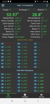
I have noticed that the inverter shows a very high battery state: 81% for 50.3V while the BMS shows 12-13% for the same value. I also had to calibrate the total BMS voltage as it was under-reporting by 0.4V. I have not done any voltage calibration for cells, can do it if needed.
 
My findings so far:

The inverter will quickly go from bulk to float charge, limiting charging current severely. I've increased the float voltage to 55.4V on the inverter and let the BMS do its job.
I cannot top balance. Even if I reduce the current a lot, some cells will reach 3.6V while most others are at 3.38V. The BMS kicks into OVP, lets the offending cell discharge to 3.5V in order to balance the others and the cycle repeats. Perhaps I should just leave float voltage to 54V, not sure.
The JK BMS will let me set 100% and 0% SoC values but these seem to be ignored. At 3V per cell, the BMS will report 0%. At 3.3V the BMS will report 100%. Not sure if I should increase the capacity from 125Ah (these is how the cells are specced) or if the BMS will auto-adjust to the real capacity in due time. These are new B-grade cells.
The inverter will happily keep draining the battery until the cutoff voltage, not following the back-to-grid voltage. The drain is around 3A, around 150W, which is what my house uses at idle. I've set cutoff to 48V, back to grid to 49V. At 48V the BMS reports 0% left.

Not sure if I'm doing something wrong here. Only 2 cycles of the battery so far.

I might build a converter unit from JK to either Pylontech or LiB or whatever protocol MPP Solar understands.
 
My findings so far:

The inverter will quickly go from bulk to float charge, limiting charging current severely. I've increased the float voltage to 55.4V on the inverter and let the BMS do its job.
Keep float at or below 3.37 V/Cell. This comes as 53.9 V for 16S system. If you want to baby your Cells, I would recommend setting float to 53.6 V instead. You will still pull basically 98-99% of your full battery capacity.

I cannot top balance. Even if I reduce the current a lot, some cells will reach 3.6V while most others are at 3.38V.
Setting full bulk voltages above 56 V is a common mistake done by people (I did it too!!) starting with an initially unbalanced battery pack. In the beginning, your bulk voltage should be low enough to stop cells from 'peaking'.
The BMS kicks into OVP, lets the offending cell discharge to 3.5V in order to balance the others and the cycle repeats. Perhaps I should just leave float voltage to 54V, not sure.
Yes. When it happens set both bulk and float voltages low such that the full cells rest just around 3.38 V and let the balancer do its thing.
It may take a day or two. Every once in a while, you will need to increment float voltage a bit as battery starts coming into balance.

There is no point maintaining a large voltage delta for balancing. Just maintain a voltage where voltage difference appears between cells.

Remember to set bulk voltage back to a higher value so that battery can charge when the Sun comes up the next day.
The JK BMS will let me set 100% and 0% SoC values but these seem to be ignored. At 3V per cell, the BMS will report 0%. At 3.3V the BMS will report 100%. Not sure if I should increase the capacity from 125Ah (these is how the cells are specced) or if the BMS will auto-adjust to the real capacity in due time. These are new B-grade cells.
Can you post a screenshot of your BMS settings page ?
The inverter will happily keep draining the battery until the cutoff voltage, not following the back-to-grid voltage. The drain is around 3A, around 150W, which is what my house uses at idle. I've set cutoff to 48V, back to grid to 49V. At 48V the BMS reports 0% left.

Not sure if I'm doing something wrong here. Only 2 cycles of the battery so far.
As long as you never let charging current drop down to zero above 3.4 V/Cell for your battery, you are mostly safe. LFP is an incredibly robust and long lasting battery chemisty.
I might build a converter unit from JK to either Pylontech or LiB or whatever protocol MPP Solar understands.
Highly recommended. I'm thinking of doing this myself.
 
Keep float at or below 3.37 V/Cell. This comes as 53.9 V for 16S system. If you want to baby your Cells, I would recommend setting float to 53.6 V instead. You will still pull basically 98-99% of your full battery capacity.
Not all cells reach 3.37V.

Setting full bulk voltages above 56 V is a common mistake done by people (I did it too!!) starting with an initially unbalanced battery pack. In the beginning, your bulk voltage should be low enough to stop cells from 'peaking'.

Now it's set to 54.1V.

Yes. When it happens set both bulk and float voltages low such that the full cells rest just around 3.38 V and let the balancer do its thing.
It may take a day or two. Every once in a while, you will need to increment float voltage a bit as battery starts coming into balance.

There is no point maintaining a large voltage delta for balancing. Just maintain a voltage where voltage difference appears between cells.


Can you post a screenshot of your BMS settings page ?

Will attach below

As long as you never let charging current drop down to zero above 3.4 V/Cell for your battery, you are mostly safe. LFP is an incredibly robust and long lasting battery chemisty.

You probably mean 2.8V? But I've figured it out, the battery is an "overachiever" and I progressively increased the capacity entry in the BMS to 135Ah. This now yields more accurate results. I thought the BMS will automatically measure the capacity and adjust itself.

1703771115290.png

The cells don't reach the intended voltage when one of them starts going away.

1703771133019.png

Not sure how healthy this is:

1703771271497.png
 
The cells don't reach the intended voltage when one of them starts going away.
Cell 4 is obviously peaking in your screenshots even at this low of a floating voltage.
You have set balancing trigger at low of a voltage which is preventing them coming into balance.
1703771115290.png
Few things you need to change in your BMS settings.
set,
Start Balance Volt. to 3.37 V.
Cell OVP even lower to 3.6 V
SOC 100% Volt. to 3.55 V
Cell OVPR to 3.55 V

Here is what you need to do exactly:
Turn balancer switch off entirely.
After the battery has almost finished charging and current begins to drop, decrease float voltage incrementally such that the voltage of Cell 4 drops to 3.39 V. Best to do this once charging current has dropped below 0.05 C at end of charging.
Turn on balancer and let the cells come into balance.

And the end of the the day, when the battery begins discharging, turn off the balancer switch until the battery gets fully charged again. Repeat the steps.

Can you post screenshot of the settings page of your charging hardware? If there is any setting related to absorption before switching to float, set it to 0 (instantaneous)
 
had to calibrate the total BMS voltage as it was under-reporting by 0.4V. I have not done any voltage calibration for cells, can do it if needed.
Check all cell volts with a meter, expecially the problem cell. It could be a BMS measurement error, or issue with connections. It's suspicious that your 0.4 voltage error corresponds to the high volt delta on cell 4.
To confirm cell 4 is not at fault reposition in the battery, it may be a bad cell.

The voltages equalize once the battery is slightly discharged and they stay equal all the way to 49V or so, didn't go below that. I double-checked everything with a meter when I built the bank.

Cell 4 is obviously peaking in your screenshots even at this low of a floating voltage.
You have set balancing trigger at low of a voltage which is preventing them coming into balance.

Few things you need to change in your BMS settings.
set,
Start Balance Volt. to 3.37 V.
Cell OVP even lower to 3.6 V
SOC 100% Volt. to 3.55 V
Cell OVPR to 3.55 V
Thank you, good catch with the balance voltage.

Here is what you need to do exactly:
Turn balancer switch off entirely.
After the battery has almost finished charging and current begins to drop, decrease float voltage incrementally such that the voltage of Cell 4 drops to 3.39 V. Best to do this once charging current has dropped below 0.05 C at end of charging.

That's difficult to do. It literally takes 100 presses of that button to decrease .1V on the inverter. The app doesn't allow you to change this either, I suspect it's a bug.

Turn on balancer and let the cells come into balance.


And the end of the the day, when the battery begins discharging, turn off the balancer switch until the battery gets fully charged again. Repeat the steps.

Can you post screenshot of the settings page of your charging hardware? If there is any setting related to absorption before switching to float, set it to 0 (instantaneous)

The settings are spread all over, but the bulk voltage is set to 56.4 and float to 54.1. I don't know when bulk voltage comes into effect, there's no way to set SoC voltages or current or anything. I don't know how the inverter determines SoC, but I can also set bulk voltage to 54.1V.
 
That's difficult to do. It literally takes 100 presses of that button to decrease .1V on the inverter.
Try pressing and holding the button and see what it does.

In the meanwhile, if you've got a discord account or something, I can take a look at things on video.
 
Not all cells reach 3.37V.


Now it's set to 54.1V.


Will attach below


You probably mean 2.8V? But I've figured it out, the battery is an "overachiever" and I progressively increased the capacity entry in the BMS to 135Ah. This now yields more accurate results. I thought the BMS will automatically measure the capacity and adjust itself.


The cells don't reach the intended voltage when one of them starts going away.

View attachment 185474

Not sure how healthy this is:

View attachment 185475
Hmm........quick question, does your cell 04 is the first to be discharged to lowest voltage level and fastest to reach highest voltage level?
If so, then you have a "weak" cell.
 
Try pressing and holding the button and see what it does.
Does not do anything, it needs repeated presses. The range is from 42V to 60V, I think, with 0.1 increments, so 180 presses to go around. 179 presses if you want to go down .1V
In the meanwhile, if you've got a discord account or something, I can take a look at things on video.
Thank you, I might take you up on that offer.

Hmm........quick question, does your cell 04 is the first to be discharged to lowest voltage level and fastest to reach highest voltage level?
If so, then you have a "weak" cell.
As far as I have seen, no, but I haven't discharged the cells all the way in a long time, I set up the inverter to stop drawing from the battery at 49V (3.0625V) and restart at 52V. But from 3.1V up to 3.35V, the cells are within millivolts of each other., with balancing turned off.
 
Hi there
i was having the same issue with cells in my new batterybank. As i saw from your screenshot only one cell is a runner ,the rest are almost close enough. What you have to do is to put a load in that specific cell to drop the voltage and the bms allow more current to your batterybank. If you see any other cell running high do the same. This is what i have done to my system and now are perfectly balanced.
 

Attachments

  • Screenshot_20231228-122340.jpg
    Screenshot_20231228-122340.jpg
    95 KB · Views: 4
Hi @spuki thanks for the suggestion, I was planning something like that. I did not calculate what load I could use, have several power resistors around as well as several 200W tungsten lights.

There hasn't been any sun here until today, but I found several grave issues with my MPP Solar inverter; am in contact with the manufacturer but they are very slow to react:
- if "solar only" charging is enabled, battery can get discharged below the safe voltage, triggering the UVP on the BMS. The "back to grid" voltage essentially is ignored as well as the "battery cutoff" threshold.
- when the above happens, the battery shuts down, the inverter restarts and goes into overload, requiring manual intervention, even with a 3% load and the "bypass" option activated
- if the inverter is manually shut down and restarted after a day, it reverts to factory defaults, with potentially dangerous default settings
- if "solar+grid" is enabled and the current is set to 2A, the inverter will pull 10A from the grid when there is voltage present on the PV but no wattage
- if solar power is present but the load is higher than the PV wattage, the inverter simultaneously reports battery charge current and battery discharge current, while the former should actually be zero
- cannot set arbitrary voltages from the app, where this is supported (e.g. bulk and float voltages)
- inverter randomly becomes unresponsive over RS232 as well as WiFi
- limited selection of certain voltages such as "back to grid" and "back to discharge", in only 1V increments

Given the above problems, I really cannot recommend this inverter, or perhaps my unit has a random bug. Most of the severe issues seem to be related to the fact that the inverter "thinks" that the battery is charging when there is PV voltage but little or no power.
 
Back
Top