diy solar

diy solar

BMS with circuit to heat the batteries?

wrybread

New Member
Joined
Nov 26, 2019
Messages
49
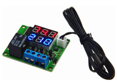
I've been reading old threads about heating pads on LFP batteries, and controlling them with controllers like this:
1652798704931.png

That has a somewhat big flaw though: you'll still be heating your batteries even when they're not being charged (at night for example). And if you don't get sun for a week you could completely drain your batteries. And since it runs from your batteries, you're then dead in the proverbial water.

I would think that a better way to handle this would be at the BMS level, which could send power to a lead if the temperature drops below X (for example 35 degrees F) AND it's charging. And the power for that lead could come directly from the charging source (in other words the solar panel). Then it would only start charging if the temperature went above X.

Is there a BMS that does that?

If not, is there some reason I'm not seeing?
 
Last edited:
I've been reading old threads about heating pads on LFP batteries, and controlling them with controllers like this:

View attachment 94909

That has a somewhat big flaw though: you'll still be heating your batteries even when they're not being charged (at night for example). And if you don't get sun for a week you could completely drain your batteries. And since it runs from your batteries, you're then dead in the proverbial water.

I would think that a better way to handle this would be at the BMS level, which could send power to a lead if the temperature drops below X (for example 35 degrees F) AND it's charging. And the power for that lead could come directly from the charging source (in other words the solar panel). Then it would only start charging if the temperature went above X.

Is there a BMS that does that?

If not, is there some reason I'm not seeing?
I am no expert on using forums. I can't tell if you got an answer to your question. I am trying to solve the same problem. Have you found a BMS device that will trigger an external relay and start a heating circuit?
 
Lifepo4 has about the same specific heat as water. A modest sized heater that can keep them warm would struggle to bring them up to temp for charging from a cold state before the sun goes down again.
 
Lifepo4 has about the same specific heat as water. A modest sized heater that can keep them warm would struggle to bring them up to temp for charging from a cold state before the sun goes down again.
nice comparison , easy to visualize, thank you.
I am considering a set up that does not let the batteries fall in temp to a point where they are difficult to heat. I do not have access to grid power. These batteries are boxed inside my uninsulated truck shell and need protection from cold when the truck is parked. I am new to this climate and not likely to be truck camping in winter. The only job the batteries will have is keeping themselves safely warm. I don't know if there will be enough sun days here in Vermont for my 600w panel array to keep up with this demand.
 
A little insulation around the batteries and heater might help.
The coldest northeast weather is usually sunny, clouds prevent radiative cooling.
If the batteries don't keep up a couple times a year do you have alternate heat? Maybe set the BMS to disconnect at 30% charge when you are away, that way there is something in the tank if you show up to a cold truck.
Something like that, think through all the possible fails and recovery scenarios and how likely they are.
 
I used to use an external temp controller to drive my 12v heating pads, but I now use the 'heater control' port on a new JK BMS to provide the same switching function. With both devices, I used an external 4-pin automotive type Relay to actually switch the "heater power" circuit from OFF to ON.
But both schemes switch on the basis of temperature ONLY, with no consideration of available charging power or time of day.

In my own configuration, I have an external manual switch to disable/enable the heating circuit, downstream from the 12v Relay. At night in a 'boondock' camping situation, I leave this second switch turned off - because any attempt to warm the batteries before about 10AM will only be consuming the power of the batteries themselves, and no charging will occur until the after the sun has come up. I simply wait for decent sunlight before turning that switch "on" and allowing the JK's temp sensor switch to enable charging during the day.
- - -
To answer the original question from @wrybread: No single component provides what you want at this time. But, to make JK's 'heater function' dependent on charge voltage actually being present at a test terminal, you could add this component in place of my dumb switch: https://www.amazon.com/dp/B07DS33JVJ

You would set the 'Voltage Relay Module' to leave the an output controlling circuit circuit 'open' with zero voltage whenever the test lead has less than charging voltage (in my own case, that would be 13.2V or higher). It would be closed for the case of higher voltage being present (e.g., a total above 3.3 volts per cell in my own case). When enabled, this controlled circuit is then to power the coil of the "power relay", with the JK port (a grounding port) on the coil ground of that power Relay.

Both switches must be closed for heating to occur. The JK switch chooses between battery charging (normal temperatures) and heating (too-low temperatures). The charge source will be connected to 3 things at all times: the test lead of the 'Voltage Relay Module', a switched power lead on the "Heater Power Relay", AND the "12v" battery bus.

Sometimes, when the battery pack(s) are highly charged (to more than 3.3V in my own case), the heater function might be invoked by the JK switched grounding connection - and the 'Voltage Relay Module' will also be enabling heat in this case. The battery packs will spend their own power to heat themselves (not a 'smart' idea, but they will stop doing that when the pack voltage has fallen below 13.2V.
 
Last edited:
With daytime panel power available, an MPPT solar controller will be offering either 'float voltage' or 'absorb voltage' to its LFP battery packs. When charging packs through a BMS-enabled charging circuit, that voltage will be pulled down by the batteries. But, when BMS has disabled the charging circuit, that voltage will reamin high and pass the test. (Although, in the case of heater pads pulling more power than the MPPT can supply, the pads might drag voltage down too far, creating an unwanted 'rapid-cycling' problem. That's TBD.)
 
I used to use an external temp controller to drive my 12v heating pads, but I now use the 'heater control' port on a new JK BMS to provide the same switching function. With both devices, I used an external 4-pin automotive type Relay to actually switch the "heater power" circuit from OFF to ON.
But both schemes switch on the basis of temperature ONLY, with no consideration of available charging power or time of day.

In my own configuration, I have an external manual switch to disable/enable the heating circuit, downstream from the 12v Relay. At night in a 'boondock' camping situation, I leave this second switch turned off - because any attempt to warm the batteries before about 10AM will only be consuming the power of the batteries themselves, and no charging will occur until the after the sun has come up. I simply wait for decent sunlight before turning that switch "on" and allowing the JK's temp sensor switch to enable charging during the day.
- - -
To answer the original question from @wrybread: No single component provides what you want at this time. But, to make JK's 'heater function' dependent on charge voltage actually being present at a test terminal, you could add this component in place of my dumb switch: https://www.amazon.com/dp/B07DS33JVJ

You would set the 'Voltage Relay Module' to leave the an output controlling circuit circuit 'open' with zero voltage whenever the test lead has less than charging voltage (in my own case, that would be 13.2V or higher). It would be closed for the case of higher voltage being present (e.g., a total above 3.3 volts per cell in my own case). When enabled, this controlled circuit is then to power the coil of the "power relay", with the JK port (a grounding port) on the coil ground of that power Relay.

Both switches must be closed for heating to occur. The JK switch chooses between battery charging (normal temperatures) and heating (too-low temperatures). The charge source will be connected to 3 things at all times: the test lead of the 'Voltage Relay Module', a switched power lead on the "Heater Power Relay", AND the "12v" battery bus.

Sometimes, when the battery pack(s) are highly charged (to more than 3.3V in my own case), the heater function might be invoked by the JK switched grounding connection - and the 'Voltage Relay Module' will also be enabling heat in this case. The battery packs will spend their own power to heat themselves (not a 'smart' idea, but they will stop doing that when the pack voltage has fallen below 13.2V.
Have you eliminated the heating issue if over 13.2V? I'm looking for solutions to only heat when the cells are below 35F or AND charging voltage is present. Also need a BMS capable of interrupting 1000 amps. None of the JK units that I'm aware of have an output you can program for interrupting >200A on over/under voltage scenarios.
 
Also need a BMS capable of interrupting 1000 amps.
You're going to need something with an external contactor. Interrupting 1000 amps is going to be expensive. And I wouldn't want to be any where near it when it happened.
 
With daytime panel power available, an MPPT solar controller will be offering either 'float voltage' or 'absorb voltage' to its LFP battery packs. When charging packs through a BMS-enabled charging circuit, that voltage will be pulled down by the batteries. But, when BMS has disabled the charging circuit, that voltage will reamin high and pass the test. (Although, in the case of heater pads pulling more power than the MPPT can supply, the pads might drag voltage down too far, creating an unwanted 'rapid-cycling' problem. That's TBD.)

Yep. Avoiding the BMS disconnect should be the priority as well.

The settings required exist in the charge controllers I have been using (EPEver) to set the absorb time and the float voltage. Also however it has a "boost recon" setting. Should the sun go away, night fall, whatever and the batteries go below that value the charge phase will switch to boost.

Tweaking those settings will help. Personally I left mine at 13.6V float. What tends to happen on a "battery full" event, the combination of the cells current tappering at 14.40V and the BMS active balancer wasting some power the MPPT backs off and the pack settles to top balance for an hour. Then it cuts to 13.6V. Immiedately the charge current falls to zero and after a period of time the loads bring the pack down to 13.6V where the MPPT picks up the loads - so to speak. Net battery current is nearly zero and most of the panel current is going straight to the load. This phase is highly efficient, even more efficient that charge/discharge of the LFPs.

You can of course end up with more than one boost phase in a solar day, which some people dont like, but you can tune it out by lowering the recon voltage.
 
Last edited:
Back
Top