silverstone
Solar Enthusiast
- Joined
- May 3, 2022
- Messages
- 1,092
I managed to start up my system and do some preliminary testing with AC (I could quickly run an air-air heat pump as a load ~ 1.5 kW).
My setup is as follows:
- 3 Inverters connected in Parallel (Master 01, Slave 02, Slave 03)
- Inverters are all Deye SUN-12K-SG04LP3-EU
- 3ph+N Grid (380-400VAC Phase-Phase, 220-230VAC Phase-Neutral)
- Off Grid ("Load" / "Backup") only
- Grid Connection is left open - Couldn't find an authorized electrician to do the job so not much choice there
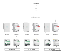
Each Inverter is protected by a 4P 32A MCB as well as a 300mA Type A RCD.
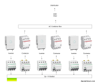
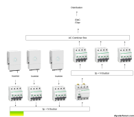
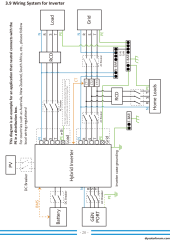
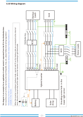
According to Deye Diagram, 3.10 should be applicable.
3.9 provided as a reference for a possible theory ...
This one looks like my setup:
Attached is my simplified schematics in PDF.
I EXPLICITELY BOND Neutral+Earth in my "AC Combiner Box" (it's essentially a combination of terminal blocks, contactors for switch-over to grid if Inverter fail, EMC filters) by putting a Jumper between thee Neutral Terminal Block and the Earth Terminal Block.
HOWEVER, I just had a realization that I might be doing it wrong: I am bonding AFTER (from the Inverter point of view) the MCB & RCD.
Therefore, if a Breaker/RCD trips or I manually switch it off, the Inverter will effectively be an IT system with Neutral NOT referenced to Earth.
Which is not the IT system that the manual refers to. In a normal European Electrical System, Phase-Phase Voltage is always 380-400 VAC.
For a TT or TN-S system, the Phase-Neutral Voltage is 220-240 VAC. For an IT system, the Phase-Phase Voltage will always be 380-400VAC, it's the Phase-Neutral Voltage which might, in a IT system, go up to 380-400 VAC !
The usual option advocated typically for Sunsynk hybrid inverters (use a contactor to connect Neutral & Earth at the Inverter side) are not really needed, since I never have the Grid connected. However, even if I were to do a permanent Earth-Neutral bonding at each inverter, it still would NOT work, because then I will have problems with ground loops (e.g. current from one inverter looping through the earth bar instead of coming back through its Neutral wire) due to having multiple Inverters.
A potential solution would be to keep the setup as-is, then add a neutral-earth "pull-down" resistor of say 100 Ohm.
Another solution (but more difficult to implement - no space, no alternative busbar on hand) is to use a feedback signal from each Breaker/RCD and based on that, close a Neutral-Earth contactor on the Inverter side. Still no place for a contactor box ...
But given the Schematic of 3.10 from Deye manual, it looks like it doesn't even need a Neutral-Earth bond . Why would they say "do not connect" in Schematic 3.9 (I assume TN-C-S supply) on the "Load" Port otherwise otherwise ? I assume in 3.9 it's forbidden because it would create a ground loop, should you connect the PE wire to the "Load" Port.
But then again my (very limited) testing of ~ 1.5kW (~ 6A) didn't cause any trips. That could be because the RCD combined allow up to 3x0.3A = 0.9A of unbalance but still ...
Does anybody else have similar experiences ? How did you solve it ?
I am NOT afraid of the protection of people & downstream equipment - That's what the bonding in the AC combiner box is for. What I'm afraid is the inverter getting damaged by having an unexpected IT system all of a sudden (if AC Breaker/RCD is open).
I actually could hear a small buzzing noise as I turned off an RCD (only once - didn't happen since then, knock on wood) ... Not sure if it was just current switching from one inverter to the other, some relay operating, ...
My setup is as follows:
- 3 Inverters connected in Parallel (Master 01, Slave 02, Slave 03)
- Inverters are all Deye SUN-12K-SG04LP3-EU
- 3ph+N Grid (380-400VAC Phase-Phase, 220-230VAC Phase-Neutral)
- Off Grid ("Load" / "Backup") only
- Grid Connection is left open - Couldn't find an authorized electrician to do the job so not much choice there
Each Inverter is protected by a 4P 32A MCB as well as a 300mA Type A RCD.
According to Deye Diagram, 3.10 should be applicable.
3.9 provided as a reference for a possible theory ...

This one looks like my setup:

Attached is my simplified schematics in PDF.
I EXPLICITELY BOND Neutral+Earth in my "AC Combiner Box" (it's essentially a combination of terminal blocks, contactors for switch-over to grid if Inverter fail, EMC filters) by putting a Jumper between thee Neutral Terminal Block and the Earth Terminal Block.
HOWEVER, I just had a realization that I might be doing it wrong: I am bonding AFTER (from the Inverter point of view) the MCB & RCD.
Therefore, if a Breaker/RCD trips or I manually switch it off, the Inverter will effectively be an IT system with Neutral NOT referenced to Earth.
Which is not the IT system that the manual refers to. In a normal European Electrical System, Phase-Phase Voltage is always 380-400 VAC.
For a TT or TN-S system, the Phase-Neutral Voltage is 220-240 VAC. For an IT system, the Phase-Phase Voltage will always be 380-400VAC, it's the Phase-Neutral Voltage which might, in a IT system, go up to 380-400 VAC !
The usual option advocated typically for Sunsynk hybrid inverters (use a contactor to connect Neutral & Earth at the Inverter side) are not really needed, since I never have the Grid connected. However, even if I were to do a permanent Earth-Neutral bonding at each inverter, it still would NOT work, because then I will have problems with ground loops (e.g. current from one inverter looping through the earth bar instead of coming back through its Neutral wire) due to having multiple Inverters.
A potential solution would be to keep the setup as-is, then add a neutral-earth "pull-down" resistor of say 100 Ohm.
Another solution (but more difficult to implement - no space, no alternative busbar on hand) is to use a feedback signal from each Breaker/RCD and based on that, close a Neutral-Earth contactor on the Inverter side. Still no place for a contactor box ...
But given the Schematic of 3.10 from Deye manual, it looks like it doesn't even need a Neutral-Earth bond
But then again my (very limited) testing of ~ 1.5kW (~ 6A) didn't cause any trips. That could be because the RCD combined allow up to 3x0.3A = 0.9A of unbalance but still ...
Does anybody else have similar experiences ? How did you solve it ?
I am NOT afraid of the protection of people & downstream equipment - That's what the bonding in the AC combiner box is for. What I'm afraid is the inverter getting damaged by having an unexpected IT system all of a sudden (if AC Breaker/RCD is open).
I actually could hear a small buzzing noise as I turned off an RCD (only once - didn't happen since then, knock on wood) ... Not sure if it was just current switching from one inverter to the other, some relay operating, ...


