diy solar

diy solar

Bonding multiple Deye 12kW inverters in Off-Grid Mode

Common RCD.
I don't see parallel RCD's working properly.
The current will never split perfectly across them.
Yeah except "parallel" in the second schematic would mean exactly that. Potentially multiplying the 300mA threshold. Is completely different from the first schematic where the RCDs are essentially sitting BETWEEN inverters (Series-Connected).

In the second schematic, either I have 300mA or up to 900mA RCD effectively. A bit high but still ...
 
If the inverters are creating the bond.
Don't add a permanent bond.
I still don't understand WHY they are. And WHY ALL THREE OF THEM. The "Island Mode Signal" has been UNCHECKED. So either way, there will be some current flowing between Earth and Neutral cables, between the different Inverters ...
 
I still don't understand WHY they are. And WHY ALL THREE OF THEM. The "Island Mode Signal" has been UNCHECKED. So either way, there will be some current flowing between Earth and Neutral cables, between the different Inverters ...
I wouldn't expect much (if any) current flowing between them. I wouldn't be concerned about it.
 
I wouldn't expect much (if any) current flowing between them. I wouldn't be concerned about it.
Well if they are all doing Neutral-Earth bonding as I suppose they are, the Earth wire could pickup about 75-85% of the Neutral current. Because there are like 4x6mm2 PE wire on each inverter and only 1x6mm2 for Neutral (same for each Phase).

It will NOT overload the PE wire (since it has the same cross-section as the Neutral wire), but it's definitively NOT a good practice. The PE wire is only supposed to carry Fault Current and - to some extent - EMC Current.

You could argue that me choosing multiple RCD (1 per Inverter) was a bad design decision. Besides the multiple Neutral-Earth bonding issue, the EMC currents between Inverters might also be high enough to disturb the RCD.
 
Why so many ground (PE) wires?
Only one is required per piece of equipment.
It sounds like you have a lot of ground loops in your system.
 
Why so many ground (PE) wires?
Only one is required per piece of equipment.
It sounds like you have a lot of ground loops in your system.
It's not a ground loop unless neutral-earth is bonded in multiple points. As I said, normally PE is NOT supposed to nor conducting any current.

And it doesn't change much if I have 1, 2, 3 or 4 PE wires on the same equipment. All it does is reducing the resistance of the connection. And provide some kind of redundancy if e.g. one connection is not properly making contact.

The fact that the Neutral current is being (partially) diverted through the PE wire is due to MULTIPLE BONDING points (Neutral-Earth), NOT the multiple PE wires. Although multiple PE wires might increase the amount (in %/A) of diverted current since the resistance of the PE connection is lower compared to the Neutral, as said before.

Why multiple PE wires ?
- 1 on Grid Terminal Block (as according to Manual)
- 1 on Load Terminal Block (currently disconnected while trying to see if this was causing the multiple Neutral-Earth issue, which caused the RCD to trip)
- 1 on Generator Terminal Block (currently disconnected while trying to see if this was causing the multiple Neutral-Earth issue, which caused the RCD to trip)
- 1 on Frame/Chassis (as according to Manual)

In the latest version of the Manual they don't show this internal Neutral-Earth bonding contactor anymore in the Schematic, so not sure what is going on.
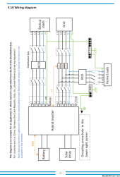
1698079659466.png

I just hope that the modifications regarding RCD and Breakers will fix the Issue. I'm not a fan on reworking 100 times on the same panel. Just removing the PERMANENT bonding jumper was an absolute nightmare.

The EMC filter might also be causing sporadic trips. Although, while working with the PERMANENT BOND a few days ago (between RCD and EMC filter), that seemed to work correctly.
 
It's not a ground loop unless neutral-earth is bonded in multiple points.
A ground loop is multiple ground paths. (Creating a loop in the grounding system) which creates noise on the system.
It has nothing to do with the N/G bond. Although multiple N/G bonds can also create a ground loop.
We used to be very concerned about parallel inverters, each Creating a N/G bond. I've since changed my mind about it. These are multiple sources in parallel.
If everything is wired correctly. There shouldn't be any current flowing between the sources on the ground conductor. (Unless a neutral connection is lost)
For current to flow between them (on the ground) . It would be taking a longer, round about path. Instead of the direct path provided (by the neutral) .
With properly sized conductors, installed as they should be. This possible current should be very minimal. (Less than 1%, if any)
Well I guess only one way to find out :ROFLMAO:. I got to rewire this part of the panel and put a clamp meter on the earth wires ...
 
Another question about your system.
If I understand correctly. You have the grid connected, but turned off?
Is the grid neutral also switched off?
Depending on how the rest of the wiring is done. This neutral can also create a ground loop path. Through the grids N/G bond.
If this is also a 4p breaker that includes the neutral. Then this is not a problem.
 
One properly sized earth wire per inverter.
Ran to the main ground bar.
Well that's against the manual though... At least 2 if not 3.


But then again you could argue that 3-4 PE wires of 6mm2 each is equivalent to approx 18-24 mm2 (actually a bit better since also the inductance gets lower with multiple wires in parallel).

I would be much more afraid of ground loops with regards to control cables, measurement cables, etc, as these are typically more sensitive to noise. And sometimes the shield could carry the fault current, so you also have to watch out for that (sometimes only ground shield on one side to avoid ground loops).
 
Another question about your system.
If I understand correctly. You have the grid connected, but turned off?
Is the grid neutral also switched off?
Depending on how the rest of the wiring is done. This neutral can also create a ground loop path. Through the grids N/G bond.
If this is also a 4p breaker that includes the neutral. Then this is not a problem.
I connected the grid cable on the inverter side, but since I couldn't find an electrician to finish the job and do the paperwork, the grid connection is floating / "parked" on some 4p breakers or contactors. Thus no potential (phase or neutral) is present on the grid terminals of the inverters. Only the earth wire of the grid cable is connected to the inverter and the ground bar.

I have 4p breakers. And the ac combiner box also includes 4p contactors to do an automatic switch over from inverter to grid, should the inverter fail.

Thus the grid neutral and the inverter neutral are fully separate at all times.

If it wasn't, since the inverter neutral is bonded to earth, then the grid rcd (main panel) would trip, due to (yet another) neutral diverted current.
 
So, quick update on the situation: I reconfigured the Inverters
- Without a PERMANENT BOND
- With "Signal ISLAND MODE" ENABLED (CHECKED)
- With a Single RCD

Now the system seems to work, at least at low load (~ 1-1.5 kW). Didn't measure any diverted Neutral / Earth current since right now the load is very small for that ...
 
Hi all.

I hope someone reads this thread still.

I’m getting my two Deye 12kW 3P hybrids soon to run in parallel and I have one question.

Can I connect my entire apartment as backup load? I don’t have a dedicated wiring for backup loads so what I would do is run everything as backup load.
If I do that what will happen while I’m having power from the grid?

My current Inverters don’t have a sell to grid option so everything runs trough them. Is it same with Deye inverters for backup load?
Yes, assuming that the backup load is large enough for it. (More than likely it will be with two)
The difference between backup load and the regular output. Is that the backup will remain powered at all times.
 
Yes, assuming that the backup load is large enough for it. (More than likely it will be with two)
The difference between backup load and the regular output. Is that the backup will remain powered at all times.
Is there a limit of backup power?

Doesn’t say anything about it in manual or specs either? I will run 2 inverters in parallel and so far I have never got more than 4000W per phase on present system, although car charging was suffering from time to time to make room for other appliances.
 
Hi all.

I hope someone reads this thread still.

I’m getting my two Deye 12kW 3P hybrids soon to run in parallel and I have one question.

Can I connect my entire apartment as backup load? I don’t have a dedicated wiring for backup loads so what I would do is run everything as backup load.
If I do that what will happen while I’m having power from the grid?

My current Inverters don’t have a sell to grid option so everything runs trough them. Is it same with Deye inverters for backup load?
Yes, this is exactly how I have wired my 12k 3p's.
Do not forget to tick the "anti islanding" , so you will have an automatic ground - neutral binding when your grid fails.
Also , make sure you have enough batteries to sustain 2* 12kw..
Each inverter can pull 240A from the batteries, so make sure you have 500a of BMS/battery amps available
 
Is there a limit of backup power?

Doesn’t say anything about it in manual or specs either? I will run 2 inverters in parallel and so far I have never got more than 4000W per phase on present system, although car charging was suffering from time to time to make room for other appliances.
12k
Is there a limit of backup power?

Doesn’t say anything about it in manual or specs either? I will run 2 inverters in parallel and so far I have never got more than 4000W per phase on present system, although car charging was suffering from time to time to make room for other appliances.
If you're not pulling more than 4kw per phase, you could consider leaving 1 inverter as a cold backup..
These inverters will pull between 60 and 90 watts per inverter, so leaving 1 off will leave you with a considerable amount of kwh's per 24h not being wasted
 
Yes, this is exactly how I have wired my 12k 3p's.
Do not forget to tick the "anti islanding" , so you will have an automatic ground - neutral binding when your grid fails.
Also , make sure you have enough batteries to sustain 2* 12kw..
Each inverter can pull 240A from the batteries, so make sure you have 500a of BMS/battery amps available
I have 4x 200A, so I guess it should work.

I’ll have some time to prepare everything until my “Peter boards” arrive so my batteries can be connected to inverter.

That’s another question, can inverters run without communication to batteries?

Now I’m controlling charge, float and absorbing with HA so wouldn’t mind doing it in future…
 
Back
Top